TIMELINE AND
UPDATES
(BELOW ARE MORE RECENT
UPDATES)
4/15/13 - It's been a month since the last post and I've been
doing quite a bit of work. One thing for sure...every corner
you turn on this thing comes with a new twist! Part of this is due
to the changes I've decided to make. Start one
thing....consider another...stop, research, buy parts, finish the
second and then go back where you left off. Then do it all
over again for the next step. It's crazy and I can't wait
until it all begins to fall together. Yes, it's still pretty
early and this is the point where hours and hours of reading,
research and parts ordering slows things down.
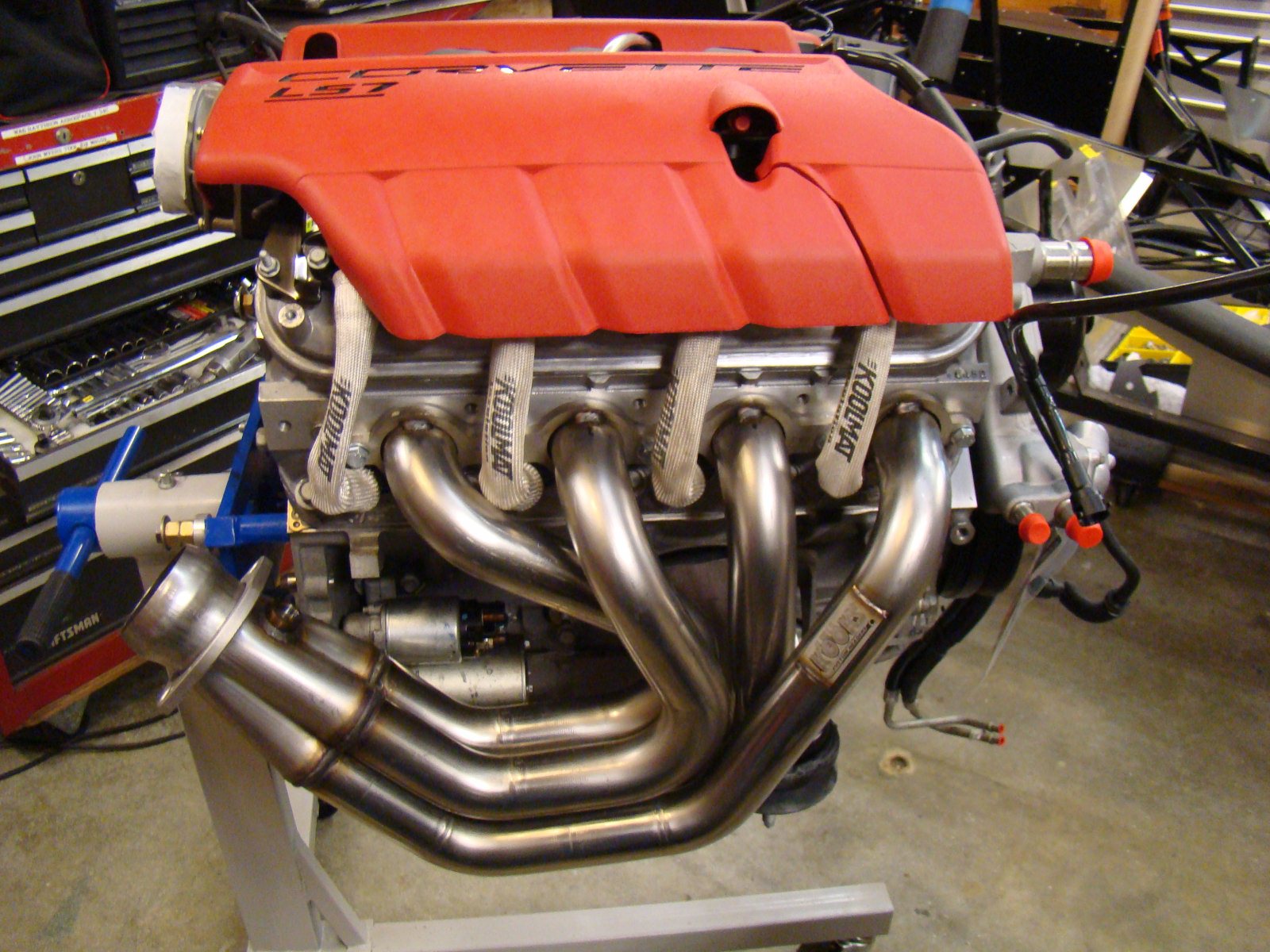
I've got the entire oil system, fuel system, race logic system
and standalone engine harness. I've also got the Cadillac
CTS-V alternator parts and AC compressor mount
and pulley. The engine
harness is completely redone (had to strip the new one
and reroute everything in order to get the wires headed in the
right direction.) It turned out pretty close to exactly what
I needed. The computer harness feeds directly from the right
side of the engine to the computer mounting area. The left
side of the harness (Gas pedal, Code reader connector and the
ignition wiring feed down the left side directly into the
tunnel.
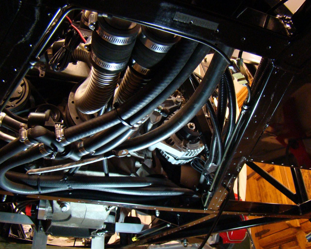
I dropped the
engine in on Saturday without issue. The AC
lines will require slight lengthening before connecting
to the compressor. I went through the cooling/heater system
and purchased the constant flow valve from "My Race Shop" and plan
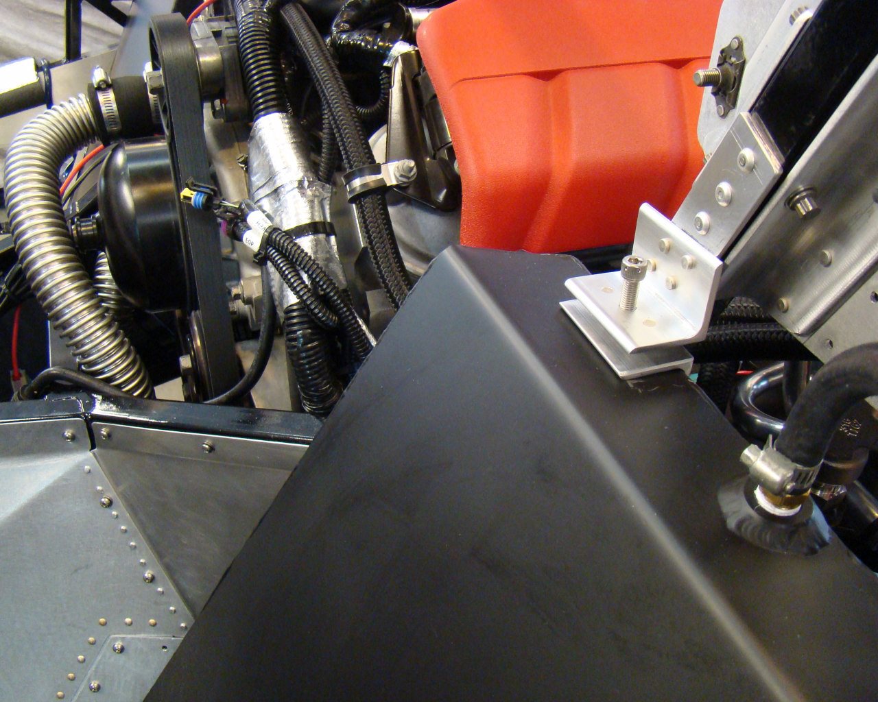
to plumb all that next. I mounted the Canton
tank on the left frame member just above and to the
right of the engine. I received the TIG welded aluminum tanks
(Quick Racing Products) and plumbing as well. So, long story
longer.....I've got what I need to actually get some work
done. Check the pages for updates.
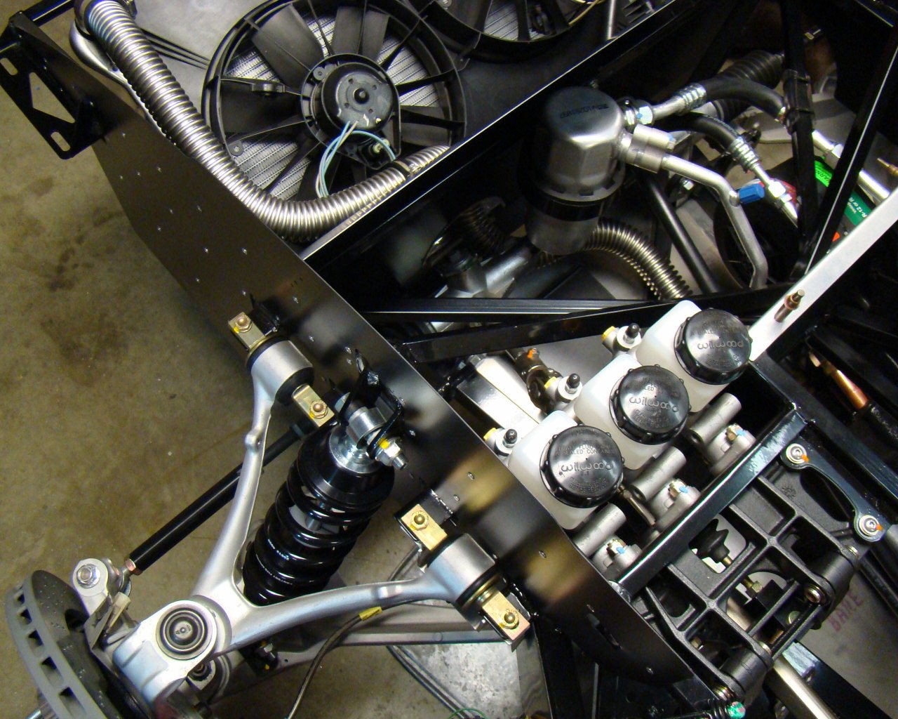
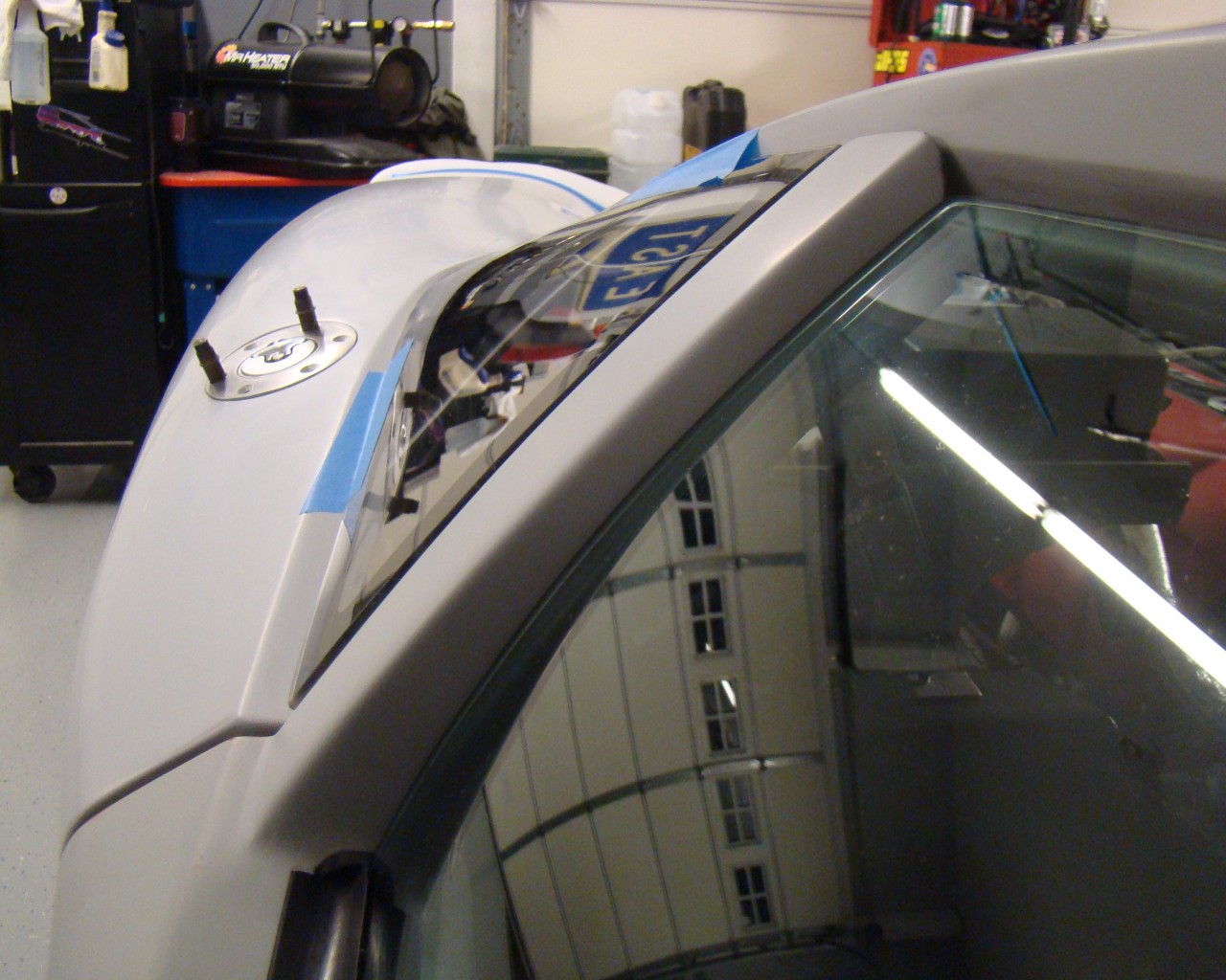
3/11/13 - CANTON TANK AND HEATER BYPASS VALVE
INSTALL:
I decided to go with the Canton Expansion tank from Summit
racing and heater bypass valve setup from "Crash" at "My Race
Shop". The picture here shows the forward overflow tank (Not the
Canton Expansion tank near the engine)These were recommendations
and seem to be the hot tip for keeping the expansion tank at the
proper level near the engine and also having proper operation of
the heating system. Some guys use an overflow tank as
well. I decided to purchase a second Canton tank to be an
overflow reservoir up front. Its a simple overflow tank with
site gauge and a petcock drain. The photos in the cooling
section show how I mounted it after verifying it would fit with the
wiper motor mounted. I'm still waiting for components for the
engine oil and fuel system so I'm not quite at the point I want to
drop the engine in the chassis. Also, I've got the LS7
standalone wiring/ECU setup on the way and will be doing some
prewiring prior to engine installation. Once the window wiper motor
is ready to be installed, I'll probably modify the aluminum wiper
mount bracket to access the cap a little easier. When I do,
I'll beef up the wiper mount by picking up adjacent chassis or
firewall mount points with custom angles/sheet
metal.
The last few weeks
have been spent on some small things here and there and getting
caught up on the parts I need for the motor. I've purchased a
Cadillac CTS-V Alt mount, Aluminum Tanks, Peterson Oil system tank,
LS7 harness/ECU, fuel system plumbing etc in preparation for engine
installation.
LATEST - Updates for the day
below. Use above index for detailed photos of all sections of the
car.
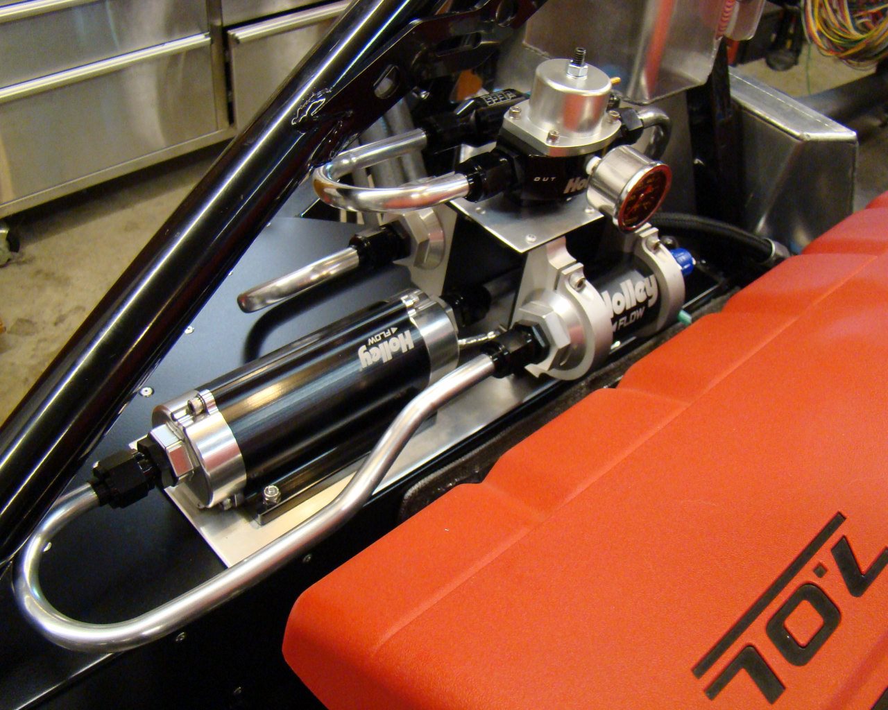
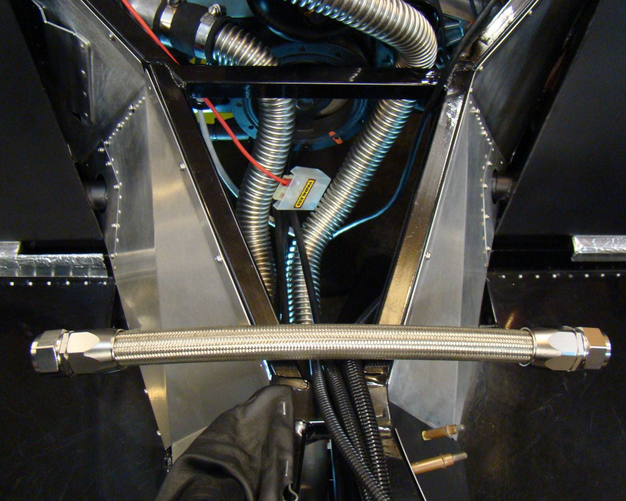
5/23/13 - Did
some additional work on the fuel system and floor panels in
anticipation of installing the fuel tanks. I re-configured
the fuel delivery system several times and ended up re-making hard
aluminum lines to route them near the canton expansion tank and to
get the entire assembly to fit on the aft left sheet metal
shelf. I've added many photos in the "Fuel" page to show the newer installation.
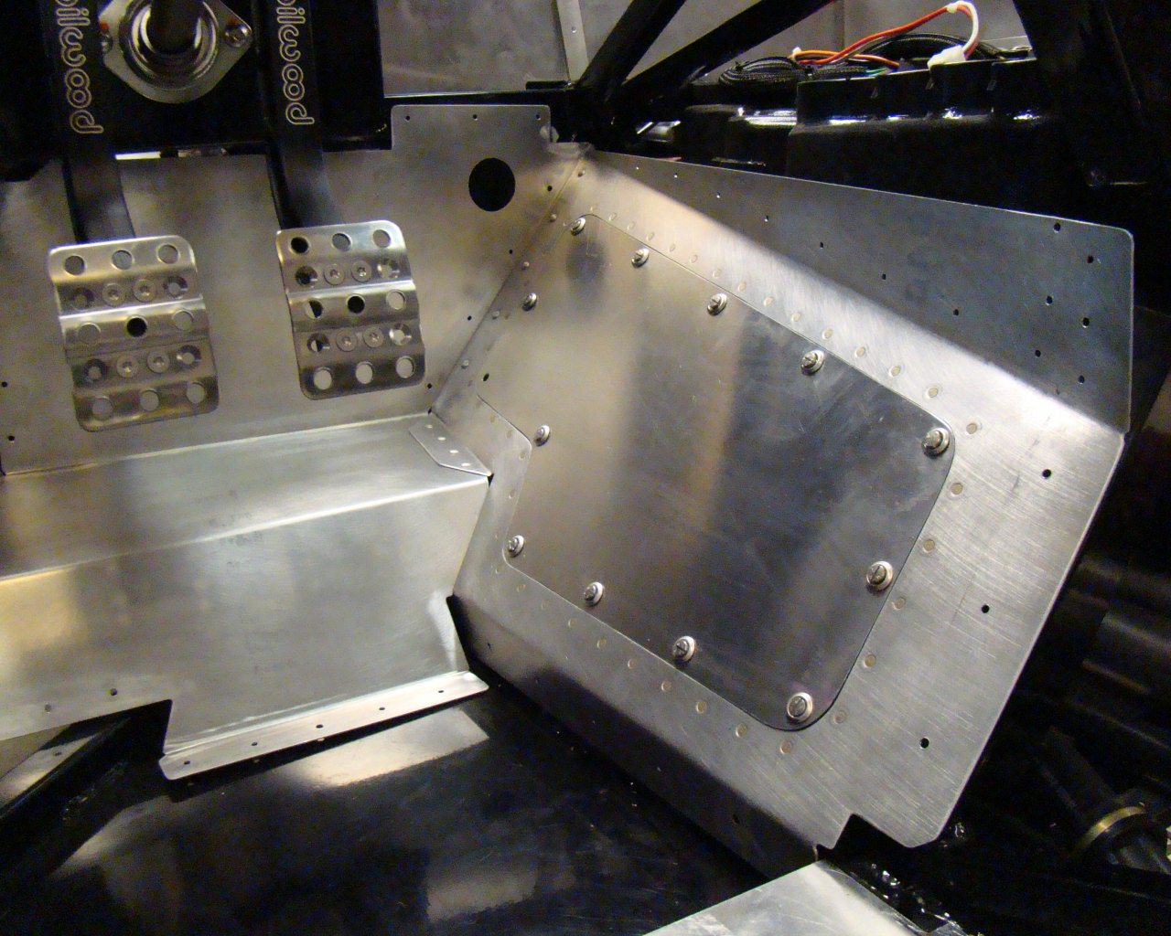
Also, I took a series of pictures aligning and drilling the floor
mount panels for the center tunnel, engine and fuel tanks.
They offer a pretty good reference for positioning and drilling the
holes. See the added ""Floor and Undercarriage" page to see the new
photos.
5/13/13 - Another
month has passed and I've added pictures in various sections of the
site. The LS7 "Harness" and "Fuel" pages have been updated
and I added a page for the Petersons dry sump tank mounting and
plumbing. Below are some pictures of the
latest.
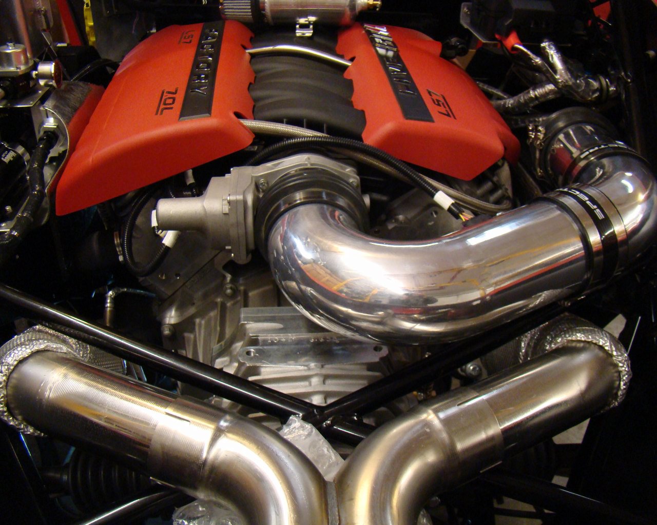
5/27/13 - Fabricated oil lines for catch
can. Also fabricated PCV pickup from AN fittings - Drilled
and tapped -12 AN coupling for LS7 PCV lines that normally go to
dry sump tank. Fabricated Corvette fuel rail cover blank-off
plates and installed Factory Five logos and
lettering.
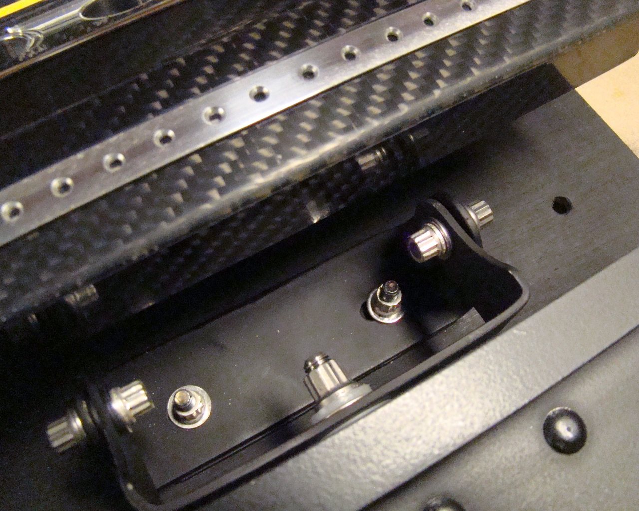
6/7/2013 - I worked a solid 10-12 hours Saturday
and Sunday on the tanks, fuel system and some odds and ends.
I decided to fabricate tank hold down brackets to help keep the
tanks from moving around. There's many different ways to keep
the tanks in place but I decided a few stops mounted to the frames
and a hold down bracket to clamp them in place would be better than
padding stuffed between the frame and sheet metal panels. I
also added a heat shield (Hand fabricated ) to keep the fuel system
cool. The system lines and filters are sitting pretty close
and above the headers. The shield helps absorb the heat and
will keep any leaks from dropping directly on the headers.. I
added appx 20 photos to the fuel
section.
7/22/2013 - Been working on the engine fuse box mount
installation. I fabricated a metal mount from several
channels and sheet aluminum so that it could be easily assembled in
place and removed for maintenance. The cats are directly
beneath the unit so I purchased 1/4" ceramic/stainless heat shield
wrap and stainless zip ties to cover the cats and keep the heat
down in this area.. Additionally, I will be installing a heat
shield directly beneath the mount plate. The bottom channel
is riveted to the frame and has nut plates at attachment points for
the secondary channel which sits on top but is offset to one side
for proper positioning of the fuse box. It can also be
adjusted. The plate mounts to the top of the secondary
channel with screws. The bottom of the fuse box is screwed to
the plate with sheet metal - self tapping screws removed from the
donor Corvette. The harness routes nicely along the underside
of the frame tube and intersects the harness for the ECU running
towards the right side of the engine between the tank and
engine. The harness for the ECU, and the fuse block combine
with rear light wiring and power cables for the fuse box. All
of these wires flow down the right side of the engine, across the
top of the thermostat housing and down into the tunnel area where
the rear #2 ISIS Powercell mounts.
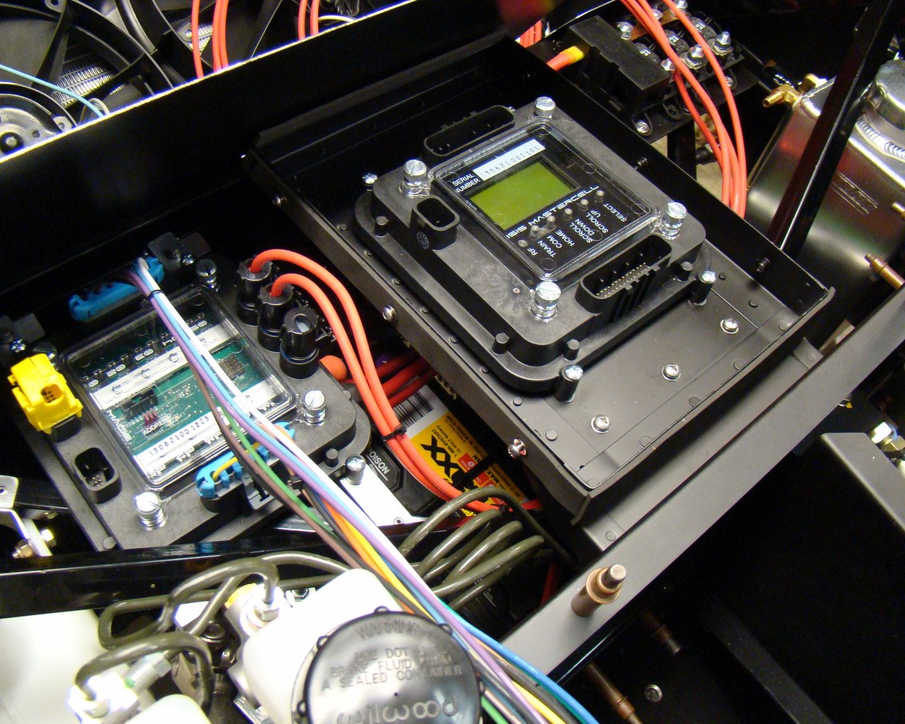
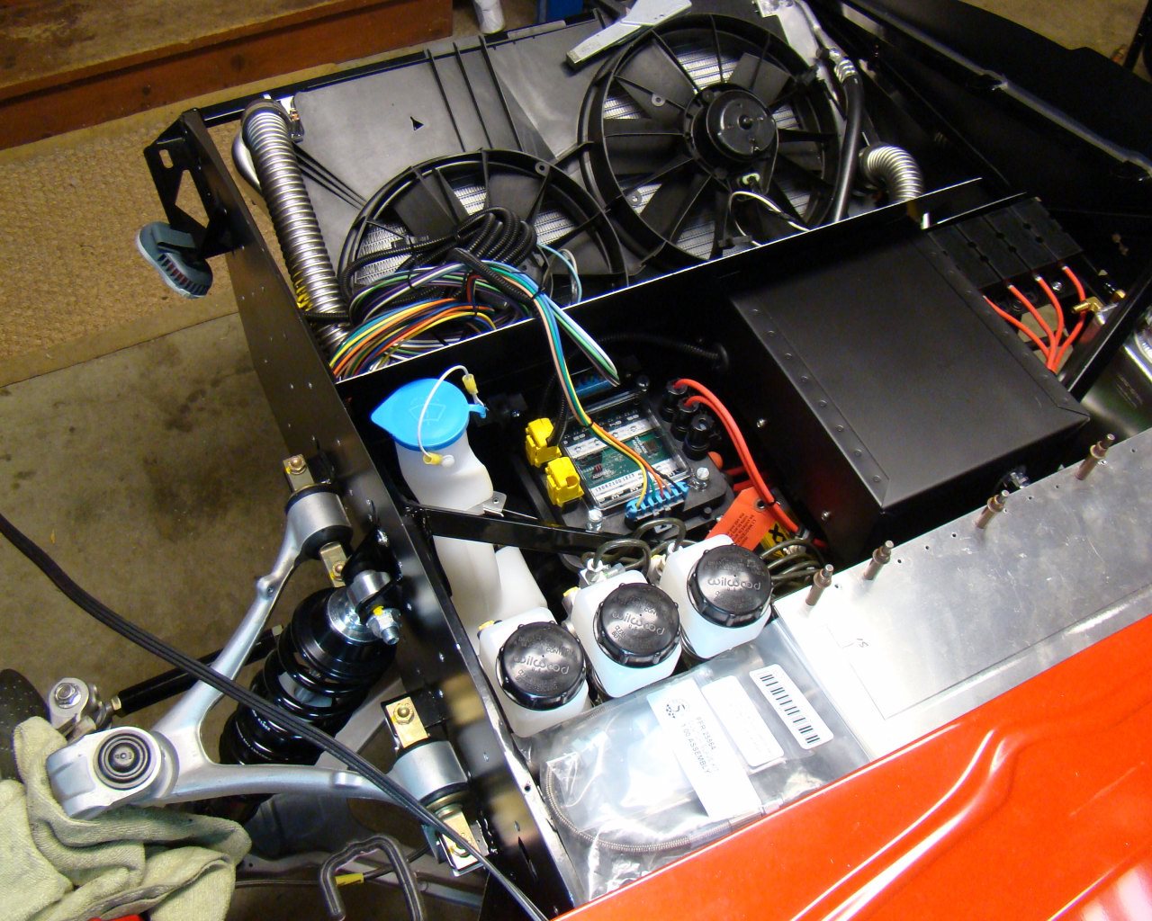
In addition to the engine harness I've been installing the ISIS
multiplexing electrical system. Much of the current status is
shown on the CHASSIS and ELECTRICAL page. Along with
completing many of the wiring schematics using AutoCAD, I've hand
fabricated the mounts, covers and brackets for the forward and aft
Powercells and have begun routing the wires.
8/12/13 - Working on
the traction control and chassis wiring. I've spent weeks
routing, re-routing, chafe proofing and insulating wiring.
I've decided to use the GM Delphi Metri-Pak plugs, terminals and
weather seals where IO can. I ordered the correct tools and
terminals from Ballenger Motorsports (http://www.bmotorsports.com/shop/ )in
Mechanicsville, VA. Un pinning the leftover C5 plugs was
easy. With the correct crimp tool, installing the terminals and
weather seals is easy and provides superior connections that are
weatherproof. I used all Metri-pak connectors for the ABS
wheel speed sensors. For the Traction Control I used aircraft
grade shielded double conductor wire. I grounded the
shielding and T.C. grounds to the chassis. I did add a page with
photos of the terminal removal and installation using the Delphi pin
extractor and terminal crimping tool.
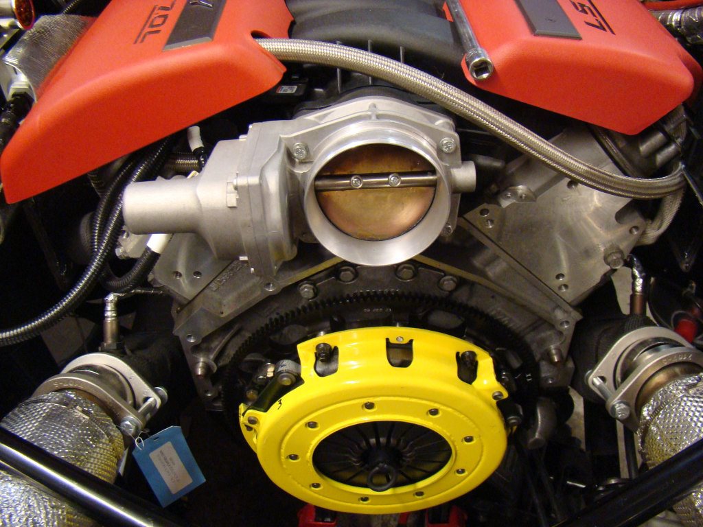
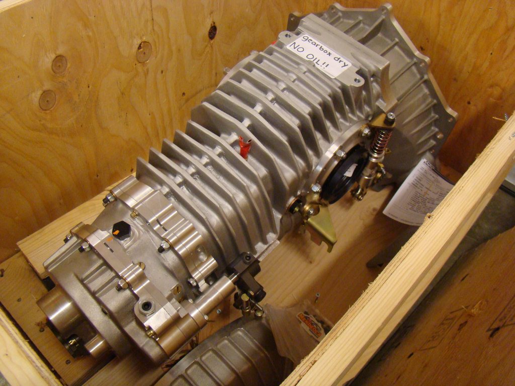
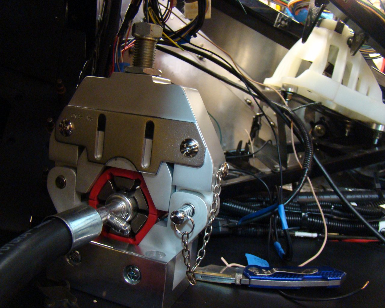
JANUARY 2014 -
Been busy doing lots since August. After a year I received
the Mendeola. It's a beautiful piece of work and mated up
perfectly. I had some slight trimming to remove material
between the throwout bearing shaft housing and clutch face.
Not a big deal and there's plenty of meat around the shaft to not
be concerned.
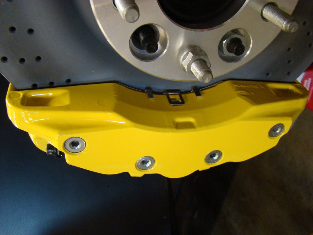
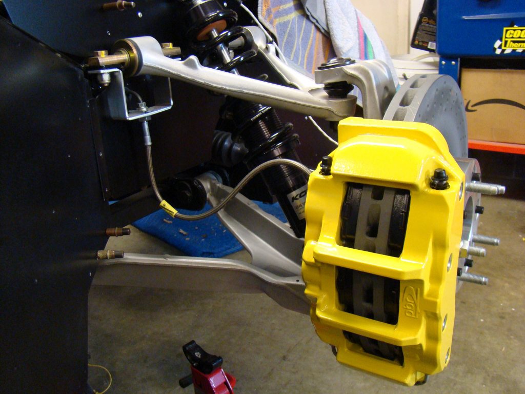
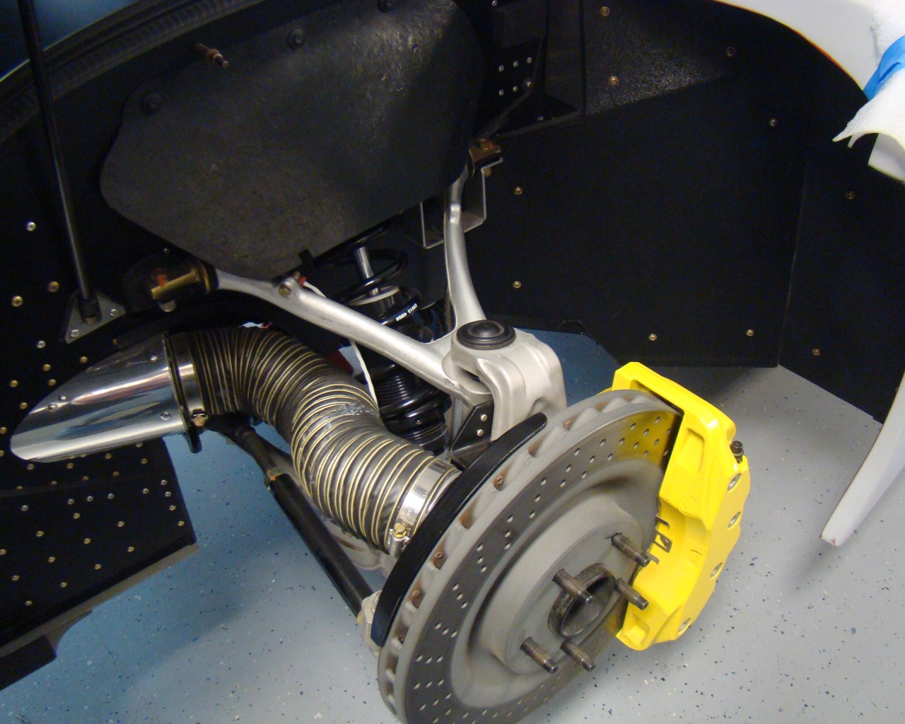
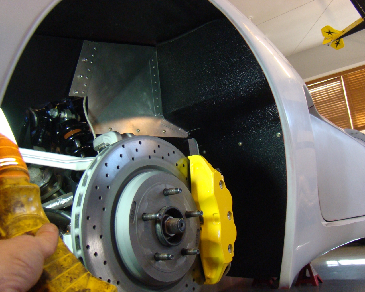
I've also done
quite a bit of work on the electric, shifter, aluminum panels and
also refinished the brake calipers in Viper Yellow Poly
paint. Clutch is in and brakes and clutch are both bled and
working. I tested the electrical, ISIS and Racelogic
system. Also cranked up the bluetooth OBDII diagnostic tester
and it worked without a glitch. All connected to a laptop so
I can finally start viewing everything on the screen. No
surprises except that on the initial ignition power check, I
cranked the engine momentarily. Apparently there was some
fuel left in it somewhere. After all the work and sitting for
a year, it started and ran for about 4-5 seconds and shut
down. Long story short....everything seems to be on track and
working like it should. I've added a bunch of photos (about
90) so make sure to check the pages for photo
updates.
February 1 2014 -
I rearranged some of the engine compartment to make room for the
intake outlet. The dual cold air intake system doesn't work
well with the Kooks exhaust so I'm ditching it for a single 4"
intake. I've added a page detailing the fabrication of the
intake (Here) to include the specific measurements needed for
proper MAF location. I've got to find a location for the dry
sump tank catch can. The relocation of the engine compartment
fuse box worked well but makes it pretty tight for the catch can
which used to be there.
April 10, 2014 -
Lots going on. I ended up sending the ISIS system back for
re-programming to accomodate the "In Net" box, giving the car a
WiFi interface for future PC based programs, flat screen and
Iphone/Android capabilities. The car electric system will be
accesible via the In Net website hardwired into a box in the
car. The system can be reprogrammed and updated via internet
downloads from ISIS Power web site. With the system, A/C and
all electrics are accesible, programmable and capable of being
turned on from any WiFi enabled device via password and user
name. The PC can run multiple Windows based programs to
include engine tuning, GPS, Mapping, Gaming, Music , email and
anything else typically used on a home PC. The unit is made
by "Stealth" systems. Memory and hard drive are solid state
and the system power supply is 12V. The interface will be a
7-10" LED touchscreen with daytime screen
readability.
11 April,
2014 - After lots of research and verification of GTM owner tire
and wheel data, I finally managed to find wheels with the look and
custom options I wanted. I decided to Go with BC Forged HB04
Concave dish wheels from Need4Speed Motor Sports in Glendale
CA. I worked with a fella named Tiko for several moths to
nail down backspacing, size and finish. Unlike many GTM's I
did not go with the traditional Corvette Backspacing or
wheels. I wanted the rear backspacing to provide clearance of
the Big Corvette brakes, with a medium concave appearance and
exactly flush with the side of the car....if not very slightly
beyond so that I can build up a slight flare of the rear fenders
similar but less than what you see on the C6 Z06 Corvette rear
fenders. Visit the wheel page by clicking on the blue links
above. I've added a link to Need4Speed on the links
page. Ask for Tiko and tell him know John sent you. Hhe
was a great help and worked late on many occasions to get my order
correct, communicating the entire time. He also knows the
business and details of options for the high end car market.
Price was excellent at about 4K for the time and ultimately the
finished product.
November 10, 2014
After quite a long break and move I'm back in
action in the garage. I've had the chance to get the garage
built which is a huge improvement over the place we were in.
I now have the room I need (plus some), good lighting and some
other things that make life nice.
Prior to the move and in antiipation of having
to move the project, I got the car running but ran into an oilissue
caused by an incorrect blockoff plate I installed over the oil
cooler supply and return. This plate was sold as a blockoff
plate for that purpose however it did not have the proper oil path
built into it. As a consequence, it prevented full oil flow from
getting to things. I had 25 PSI at cold idle. A long
story short...ithung with me for the move until I got things in
place to begin the troubleshooting process. I went through
the system, all the new components, the gauges etc and found
nothing. After researching flow a little more specific to the
oil path, I discovered the blockoff plate issue. This caused
no damage because oil still flowed in limited quantity past the oil
restrictor (which was there and undamaged as verified using a
borescope). I was halfway through pulling the engine and made
the discovery prior to unbolting the transaxle and lifting the
engine out. That last ditch effort paid off. It cost me
$10 to get the new plate. Everything is good to go
now.
I've added a page with video (Good QualityHD) of
the engine runand a walkaround of the project in it's current
state. I'll start posting pictures soon now that I've managed
to get the website back up and accesible.
More Later
NOVEMBER 14, 2014 (NEW) - Garage
Alignment video on suspension
page.
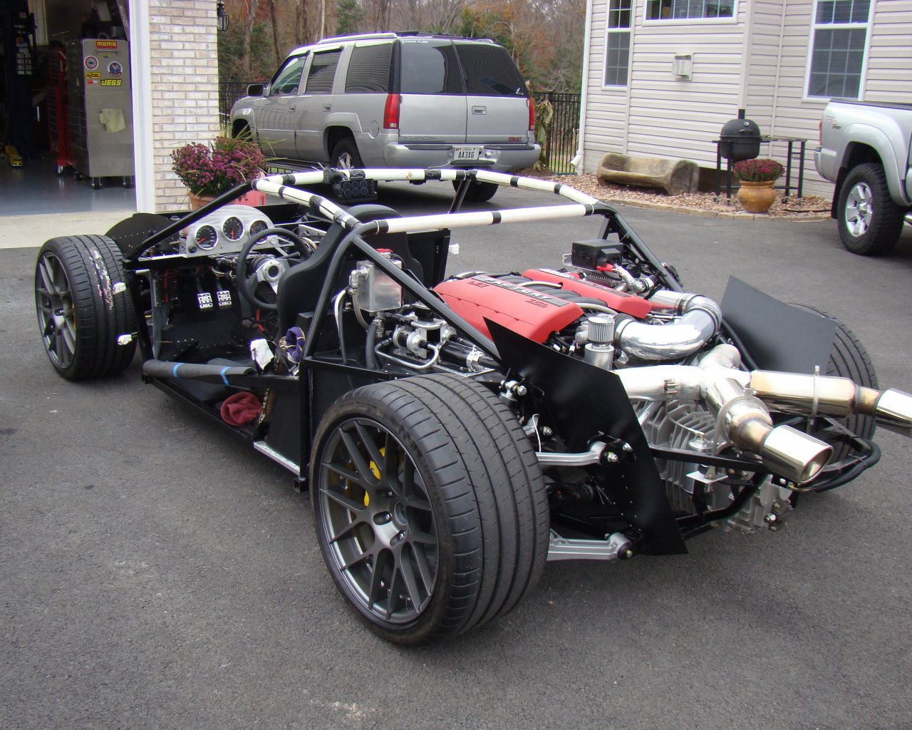
Today was the first test drive in the
go-kart. After doing a garage alignment using scales, rulers,
tape and a protractor, I set out on the road to test things
out. Everything worked as planned and of course I had gone
through everything with a fine tooth comb so I didn't expect any
issues with the engine or electrical. The main thing was to
see how the transaxle shifted and how the engine, clutch and
transaxle acted under power. It was pretty sporty. Nice
and solid and tracked perfectly at 30-40 MPH. After the run,
I let her cool down and then pulled the gauge group to begin the
body work.
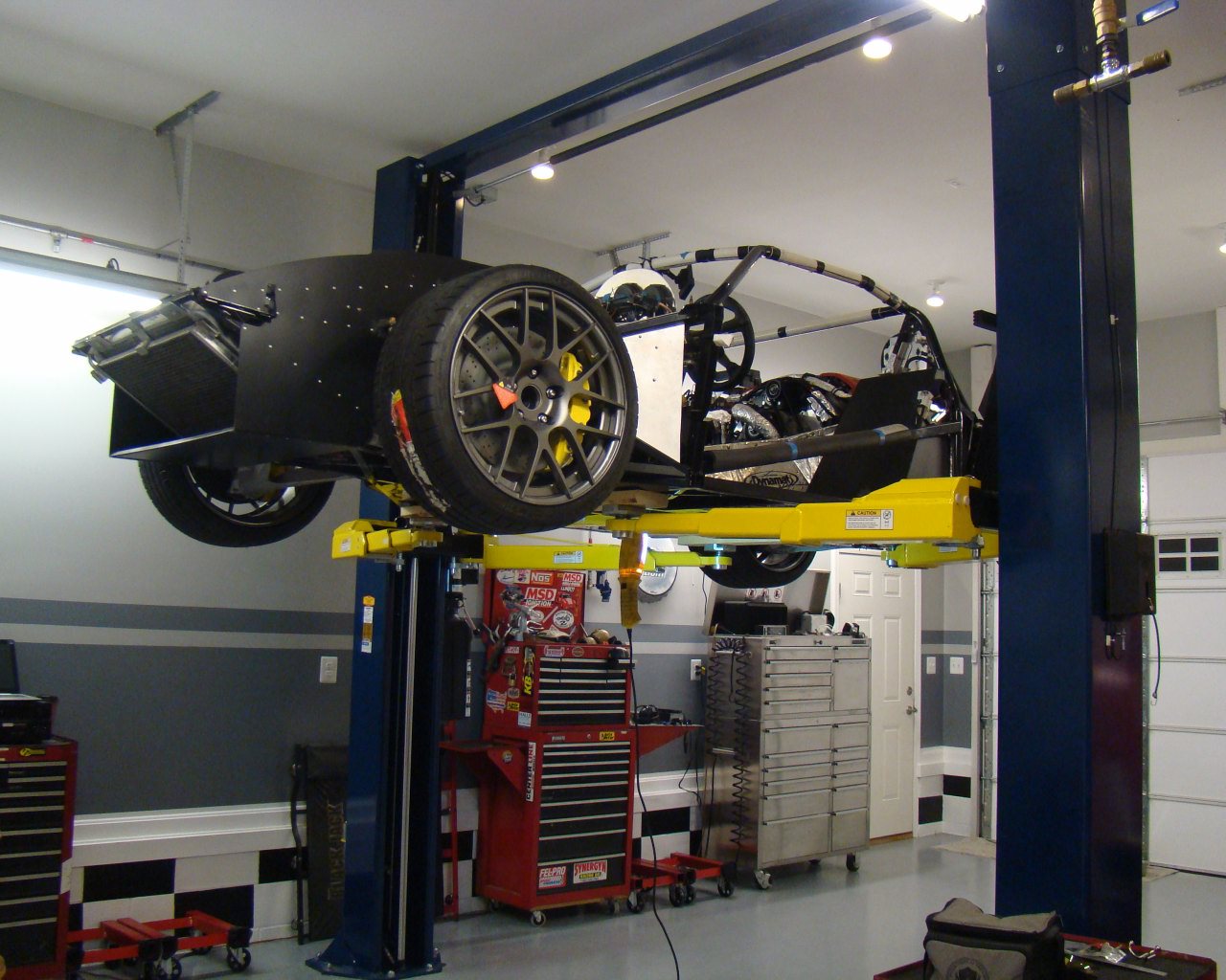
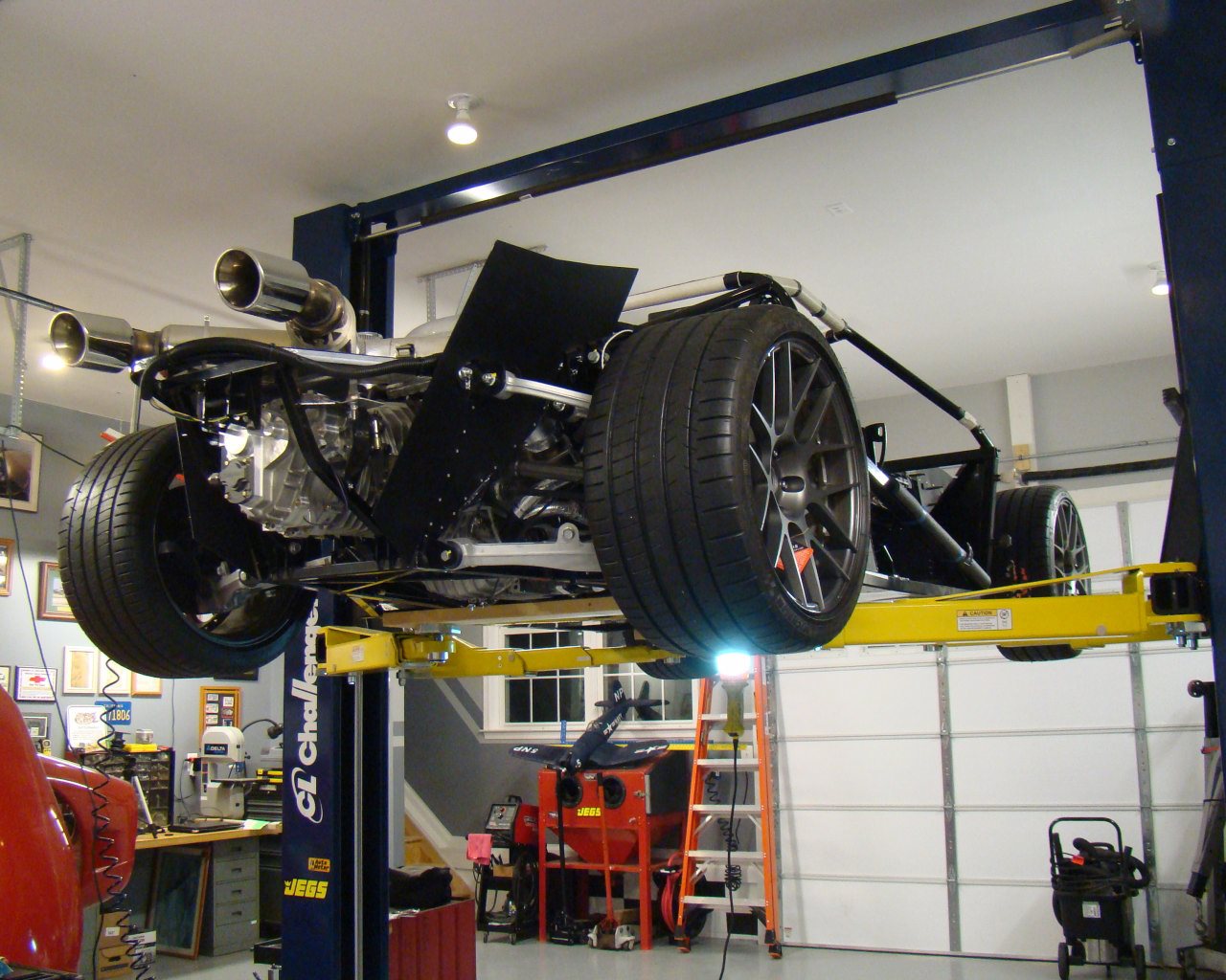
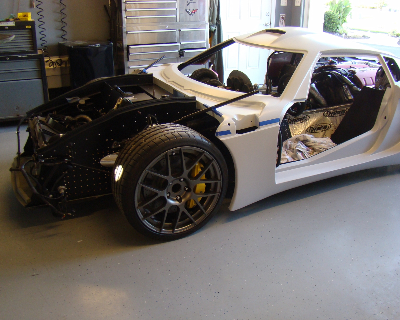
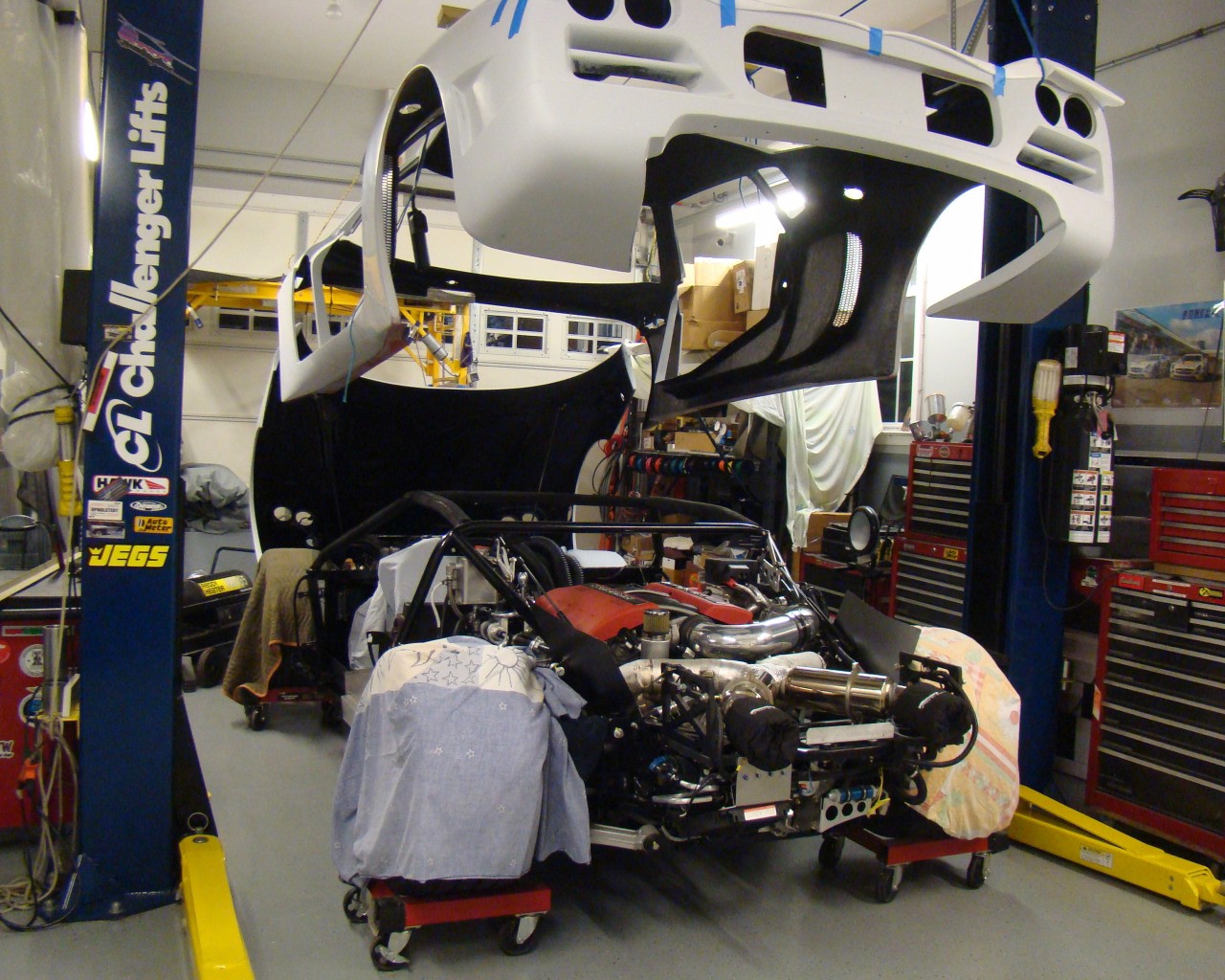
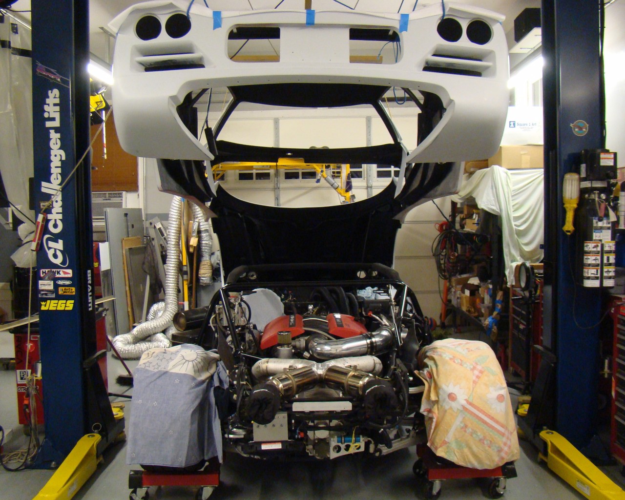
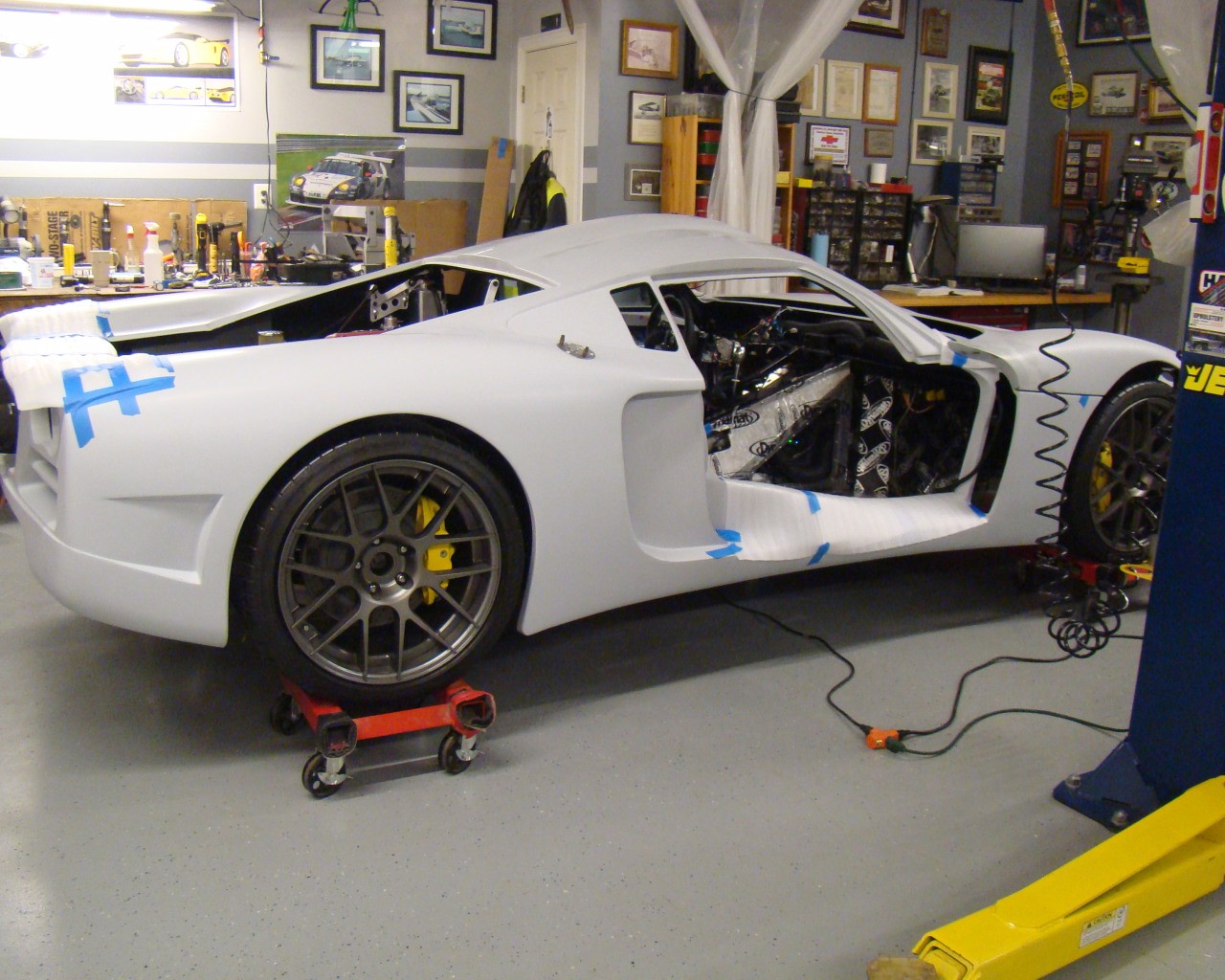
NOVEMBER 14,
2014
Here's some garage shots with the GTM
up on the new lift just prior to the test drive. I ran the
Mendeola through the gears and ended up adjusting reverse
slightly. The pictures provide a different perspective -
laying on my back with it up on the lift.
...And up on the
lift....
JANUARY 21, 2015 TEST DRIVE WITH BODY ON
BELOW
DOORS:
The time has come to play with the doors.
This is the nightmare on the GTM. Commonly known as a royal
freaking PITA. Not so much because I can't deal with it but
more the fact that FFR has not improved anything in the Gen II
after years of issues in the same area on the Gen 1 GTM. IMO,
A bit to be lacking when asking the increased cost of a kit now at
$25K.
Basically, I just threw the book back into the
bookshelf, grabbed the parts and started holding things in place,
eyeballing the more obvious things that needed to be done.
Then, step by step I walked through a completely different way to
get it done. Yes, FFR has some cool kits and yes, mass
producing door frames and fiberglass bodies that fit exactly in
every case could potentially cost a huge investment in machinery.
On the other hand, some of it could have been improved. One thing
for sure, the book needs a facelift and if there was any part of
this kit I'd ask for them to improve, it would be the book.
This is well within the costs of the increase in revenue they get
for the kit. They shouldn't rely on recommendations to go to the
forums. They don't pay for them and to do so shows a lack of
support we're paying for. Part of this frustration shows in
the number of pictures I've posted on this site. They should set up
a builders page and just load pictures and technical advice for
each of their kits. There's a thousand issues they know
deserve it and are common for each of us.
Sure, the GTM may be cheap when speaking of
Ferraris and Lambos but last time I checked 25K could buy some
pretty high quality stuff. When speaking GTM, your paying 25K
for a concept, an easel and some paint....maybe the dream.
All aside, Factory Five should make the changes and adjustments to
both the kit and the manual that by now, could have and should have
been done. The only thing that will make up for this is the dream
and the time invested in overcoming a new headache at every
turn........of the manual pages that is.
November,
2015
Its been a while
since I updated the site but there's been alot of work done on the
car. I've added a few pages and a host of new photos for the
drivers door, lights, diffuser, fender wells and Mendeola oil
cooler (Setrab w/ Tilton pump). Enjoy. I hope they
help..
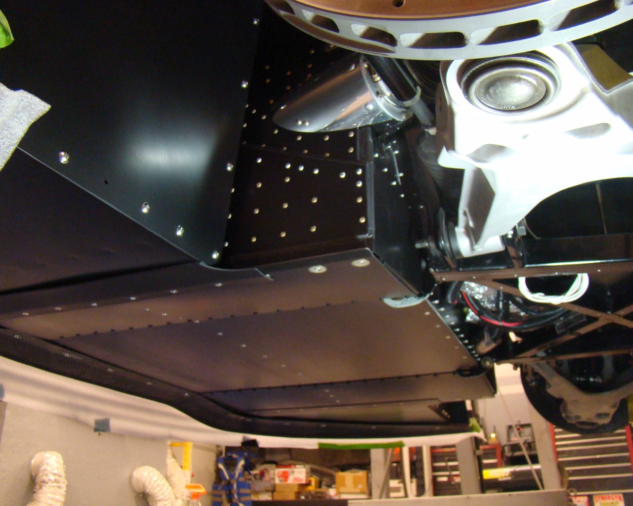
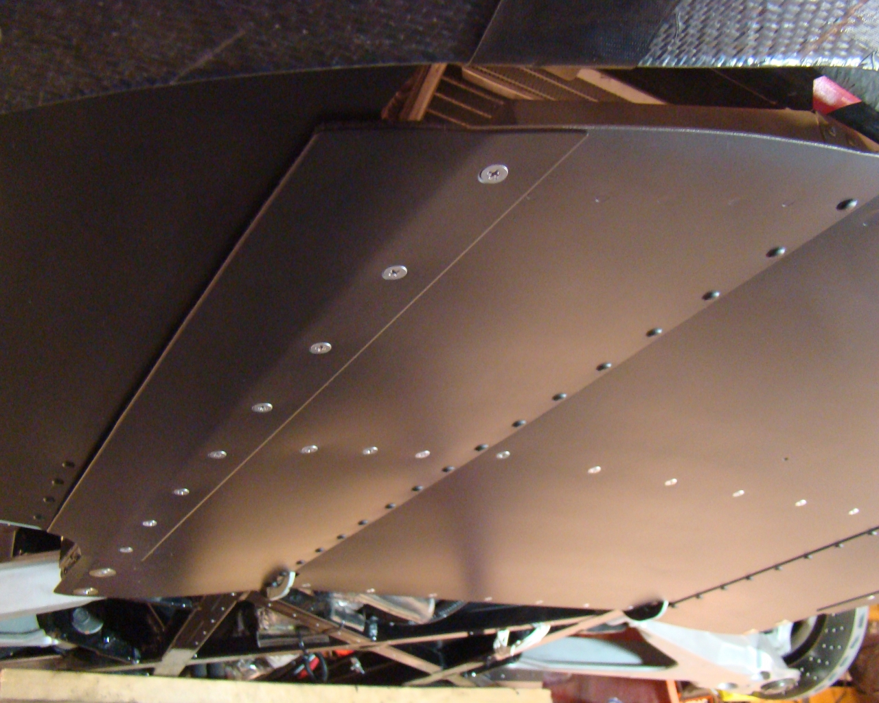
November 23,
2015
I
spent the latter two weeks this month contemplating and then
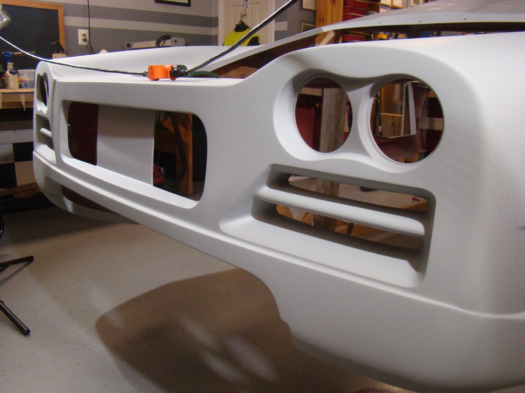
modifying the sheet metal area under the front end. This
should add considerable strentgh but also improve aerodynamics and
cooling. The below pictures show the end result of about a
week of prototyping and then forming various pieces that now make
up a removable front end belly panel that conforms to the
splitter. I used aircraft hardware and formed the pieces with
.063 and .080 6061-T6 aluminum. Check out the "Nose Sheet metal"
page for step by step buildup. BTW...I inadvertantly deleted
the photos of the very beginning which consisted of making the
templates for the .063 sheet metal 3-piece panel but you can still
see the end result. All templates for the individual pieces
were made from cardboard and traced onto the sheet
metal.
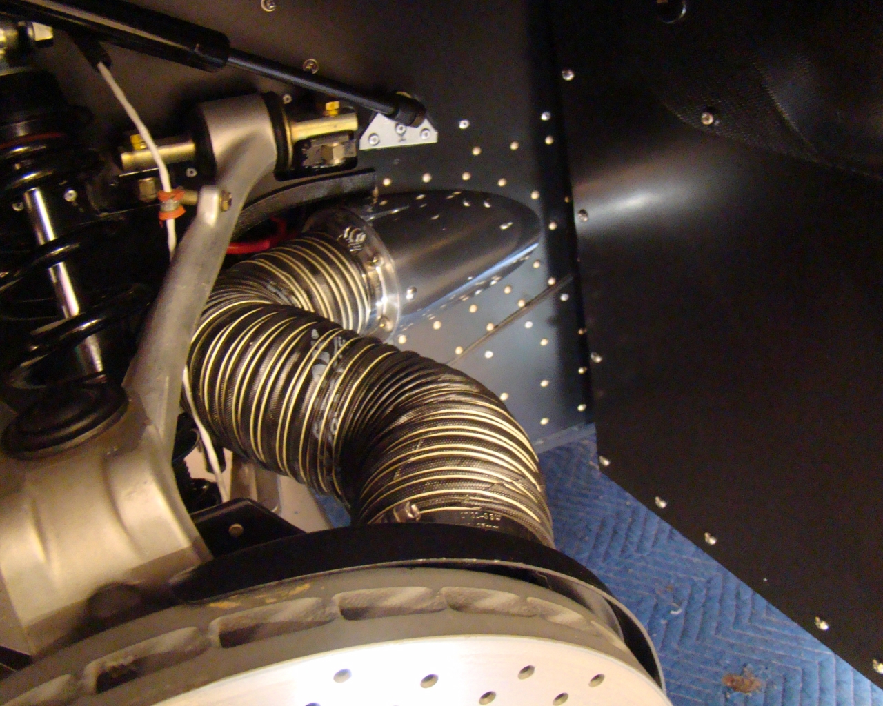
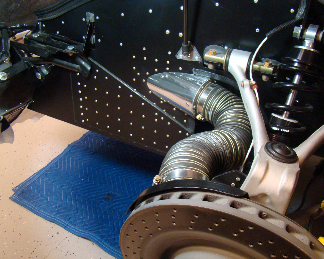
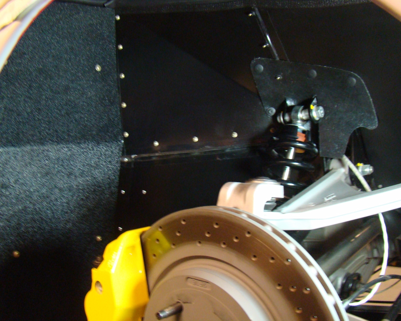
December 27,
2015
Spent a few days
designing and mocking up a brake cooling system to take some of the
excess radiator box air out. There's enough air passage
around the radiator and with all the excess cooling air above the
radiator, I was able to get this done without interfering with
steering or suspension articulation. See all the details on
the "Brakes"
page
January 15, 2016
Finished nose, forward undercarriage and brake
cooling modifications. Finished in Epoxy two part flat
primer. See "ALUMINUM PANELS" and "BRAKES
PAGE"
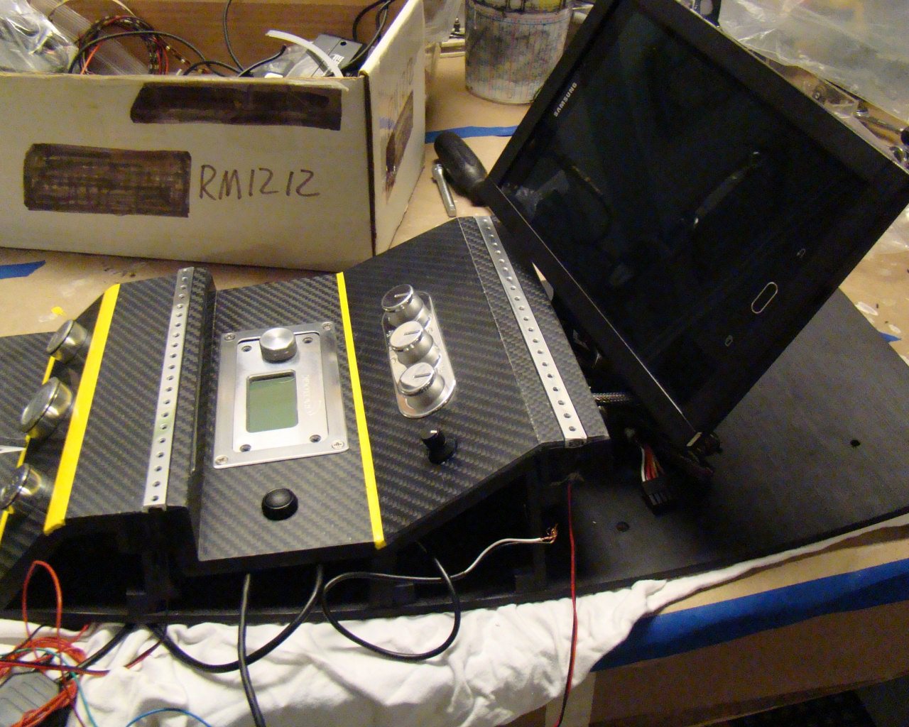
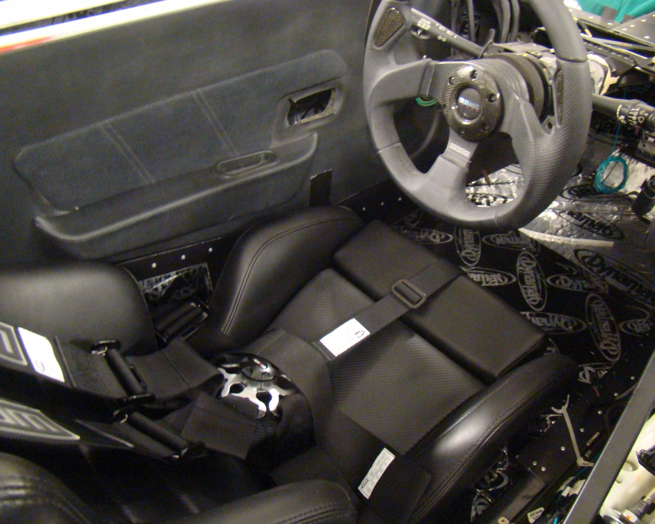
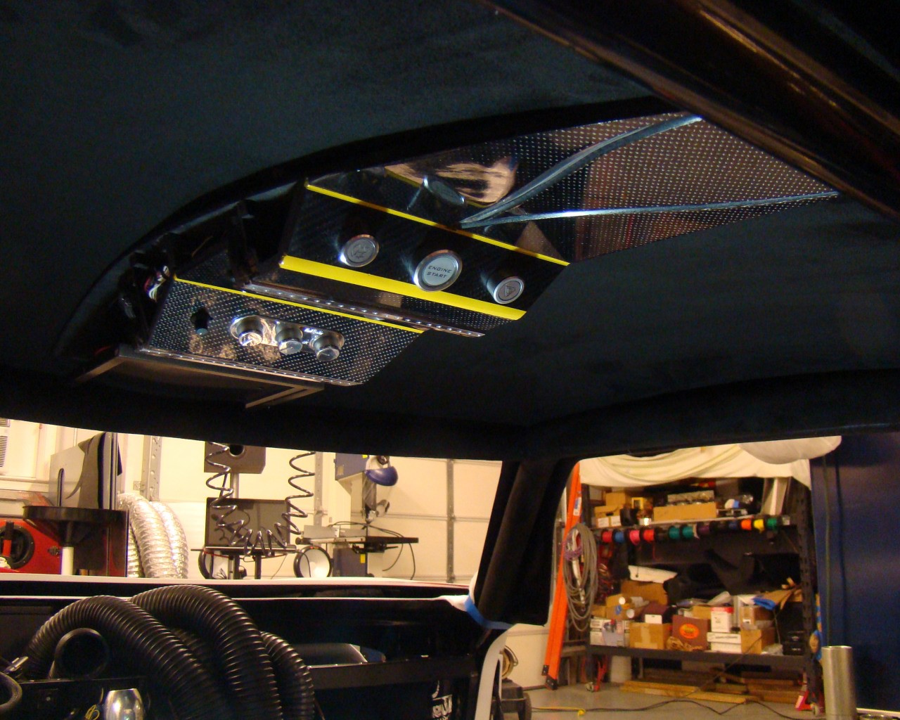
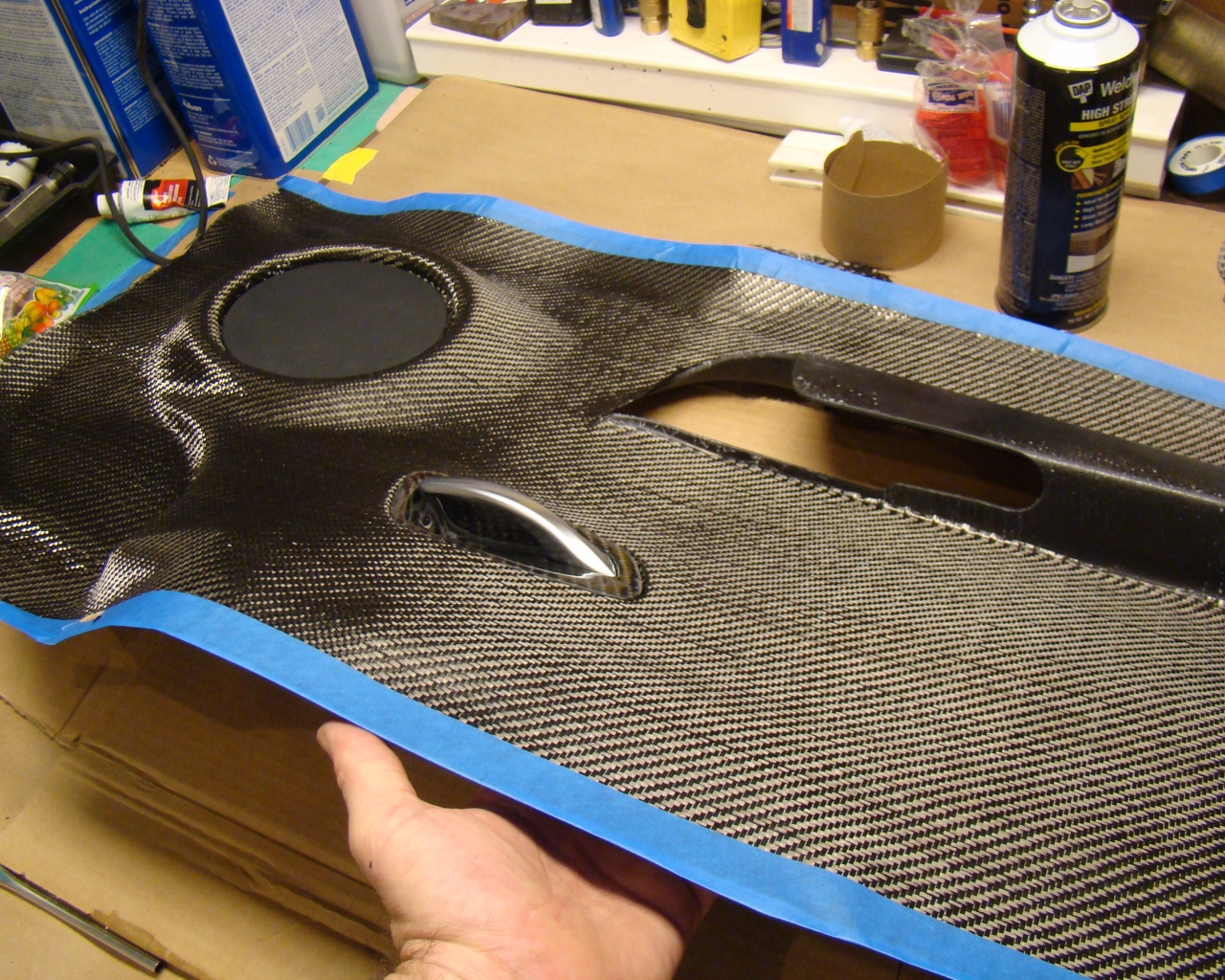
March 7,
2016,
While trial fitting the
interior I noticed the realestate was somewhat crowded for the
traction control, switches and some of the other stuff. I
figured an overhead console would be worthwhile to move some of the
stuff up to the cieling. This removes all switches and leaves
only the primary (3) gauge group and the PC flat screen I intend to
add later forward of the shifter. The tablet is a Samsung S2
with a housing I fabricated with aluminum channel. I also had
to mold the buttons. I ran a yellow stripe across the flat
Carbon Fiber after noticing some transition issues between the bond
lines of the CF. I say "Flat" because I liked the look of the
CF after hitting the gloss epoxy Gelcoat with some 1500
sandpaper. It's supposed to go with the yellow brake calipers
and yellow on black stitching I plan to have done later..
Check the "Overhead Console" page link above.
August
2016
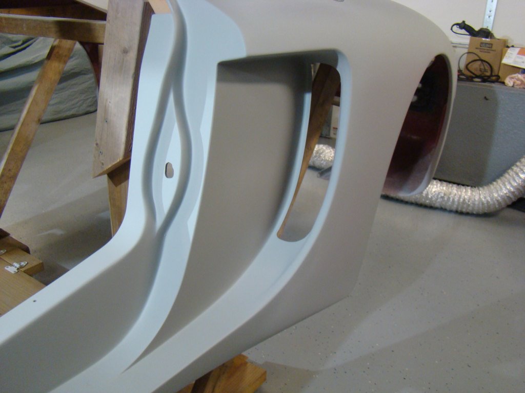
It's been a
busy summer with gardening, going to the beach and body work.
I've been fiberglassing, sanding and filling for months. Lots
of very tedious boring work....over and over.....and over again and
again with getting the lines correct, getting the roof intake
glassed on and filling in around each of the glassed on rear vents
below the lights. I'm about to spray the epoxy primer
(Metacryl) - tomorrow morning is the plan. The pictures below
are before and after the Slick Sand coat. It's very porous
put provides a nice high-fill polyester base that helps even out
the shades for sanding while providing a nice gelcoat to finish
sand. Yes, the entire body had to be sanded again from about
100 up to 500. I ended up going over the body again after the
slick sand with a fine grade filler for making minor corrections
and filling in the pits. This is alot of work! Not as much
fun as bolting things together. Gotta be patient and walk
away now and then. It goes on and on. The front end is
the next piece....then the hatch and doors.
I plan to
shoot the epoxy and then place the body back on the car. I'll
doublecheck the front and doors and then determine any last minute
corrections and paint the inside black or coat with a
bedliner. There are lots of little things to check.
Painting the body off the car may present a risk of scratching so I
may do everything except the final color off the car. Then
I'll mount it. I'll shoot the doors and hood off the car - to
include final color and clearcoat. I built a paint booth today and
plan to post pictures later.
I've added a few pictures to the "Aluminum foort Box Panel"
page
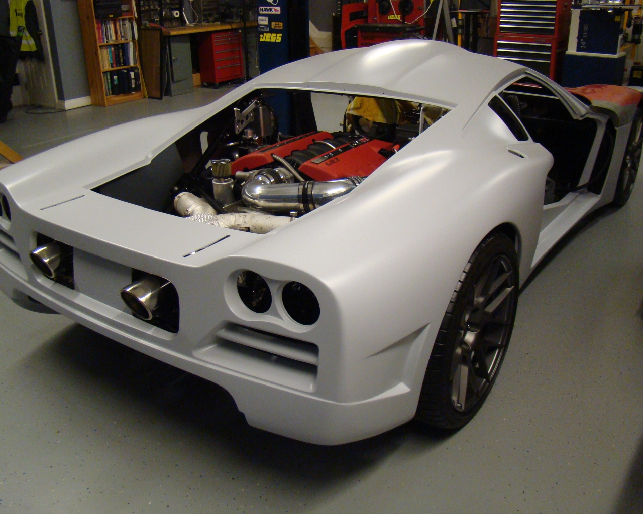
September
2016
Still
working on the paint prep prior to beginning the final fitting and
assembly. Months of sanding and my fingers are wearing
out:). Honestly, there are so many lines and curves to
blend. I use just about every imagineable sanding
block. I did glass in the hood vents and blended with the
surrounding surface. That was quite a job but worth the
pain. The other option would have been to bond them down in
the cutouts. The hard part is sanding the transition and
radiuses at each vent opening. They begin at the
surface and flow downward - 4 x for each and that means a total of
16 transitions to worry about keeping radiuses flowing correctly
and transitioning to the surrounding skin. I'm currently done
with the nose (except for final paint) and working the doors
now. All of this will be mounted one final time prior to
removing and beginning the sequence of final assembly. Looks
cool light color but I don't think I'll go that direction.
We'll see.
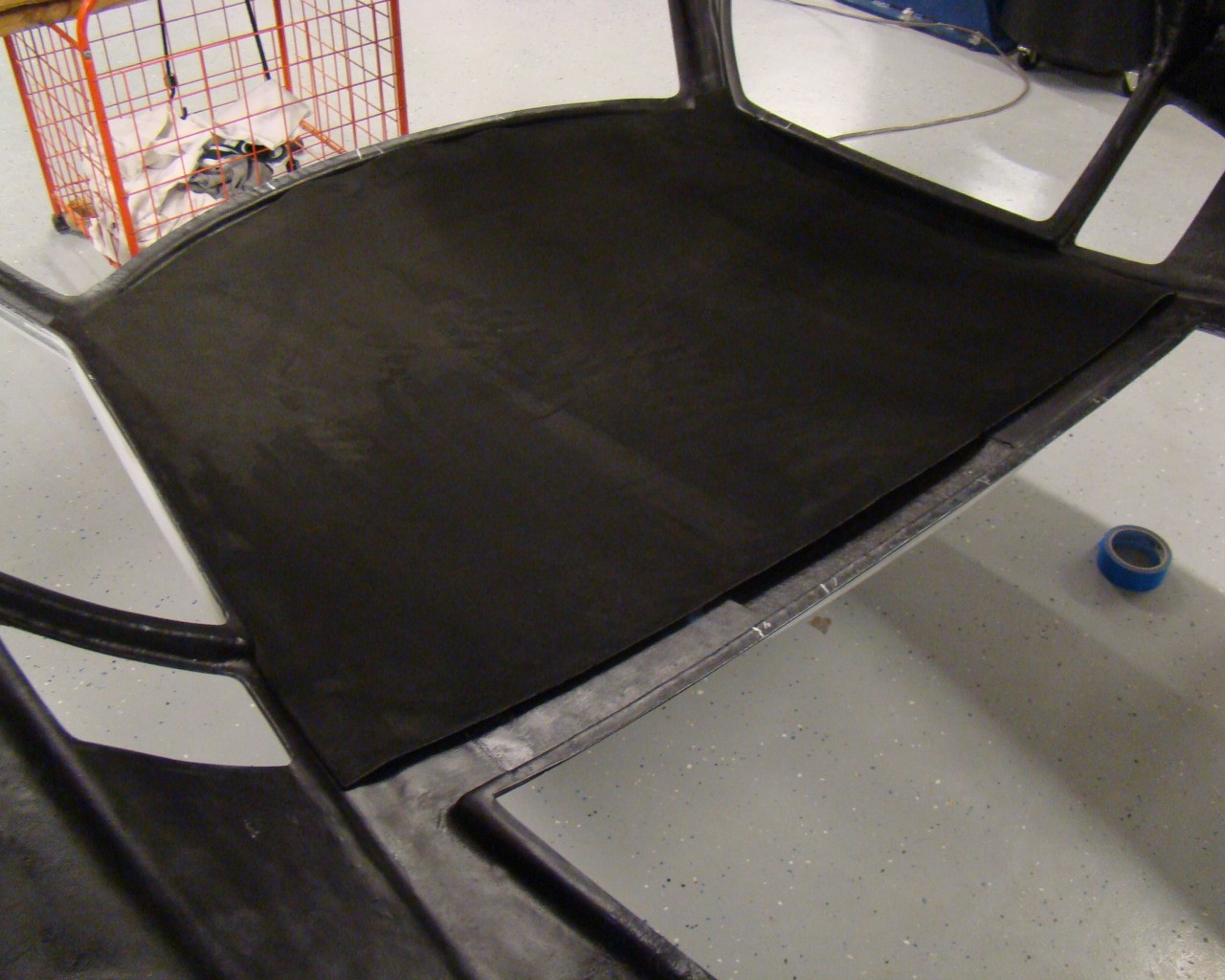
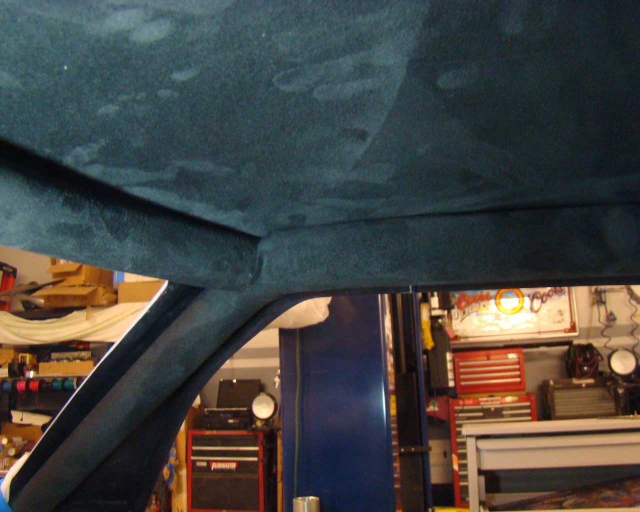
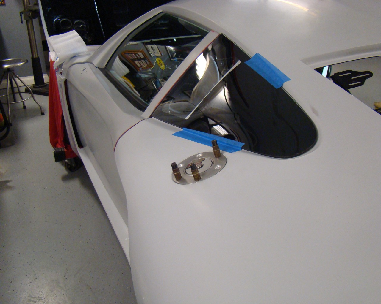
1/31/2017 Working to get this done by
late Spring. I spent some time looking at the option of
painting the body off the car but don't want to chance the issues
that come with it. Main thing is concern for damaging the
paint, door final fit issues, paint consistency of the front end,
doors and hatch and some other things. As a result I've final
sanded to 400 and mounted the body after wrapping the roll bar and
doing the headliner. Here's some snapshots. Detailed pictures
are in the appropriate places you can find in the above
pages. I added the E-Brake
video showing the replacement for the failing Corvette E-Brake
issue.
3/17/17 Spent the last two months closing out
the wheel wells and beginning pre-paint work. I chose Smokey
Granite Mica (Lexus) for the color and may do a Viper yellow
stripe. I bought the paint (Cromax) and all paint, sealer,
clearcoat and the 1/2 pint of yellow ran me $1600. As I began
going around the car I decided to doublecheck door fitment one last
time. As I took a closer look at the door panels I realized I
needed to do a little more in terms of mounting the panels before
paint. This turned into a total project to include full
carbon fiber door panels and hand built arm rests which ultimately
required vacuum bagging. Pictures are worth more than words
but I will say it took me a bit off course. What started
everything was the Corvette mirror and door controller that needed
to be mounted. That required the custom arm rest which meant
I had to strip the entire door panel material off and remove the
glue from the ABS. (Not fun but a 40 Grit disc on an orbital
basically vibrated the glue off). I welded ABS left over from
the wheel wells to do the arm rest and then covered with yellow
stitch Carbon Fiber. The panels have three layers. I
have the wheel well work photos in the "Front Fender Wells" page
and the door panels and arm rests in the "Interior" page. The
door handle was relocated and molded into the stock door
panel. I used the older panels that had the separation issue
with the material. I still have the improved set -
untouched.