LS7 INTAKE
REVERSAL AND CONFIGURATION
LS7 INTAKE
REVERSAL AND CONFIGURATION

The sequence of pictures ends here with current progress. The last photo (way down below)is where it started. Many are simply posted here for reference.
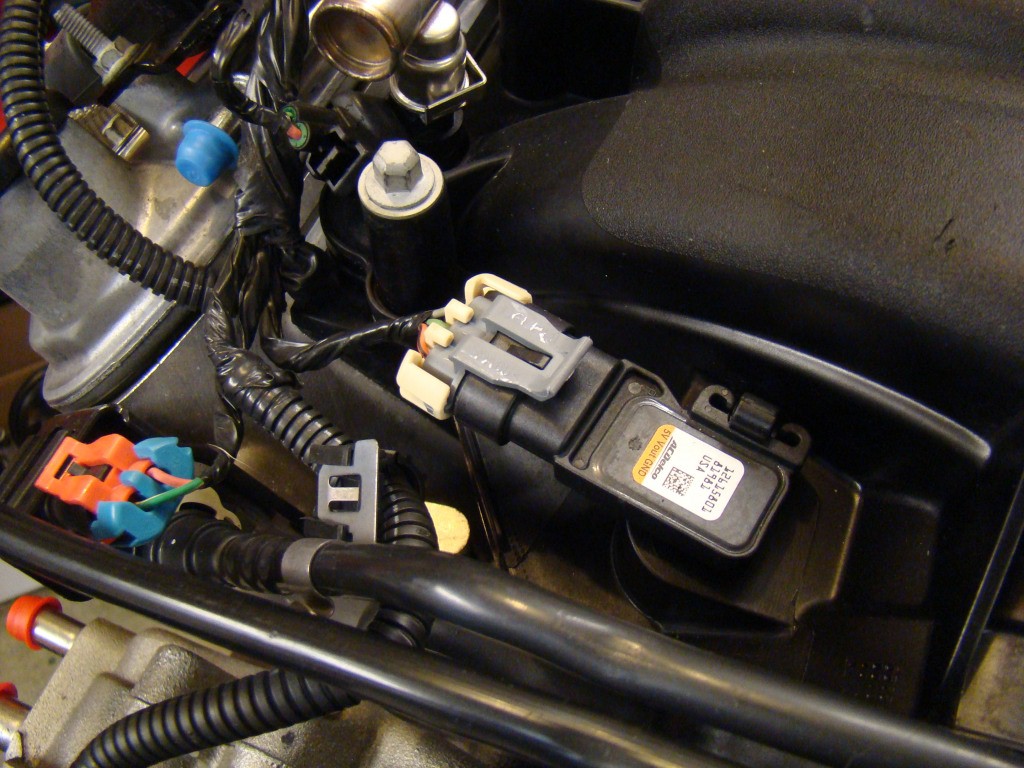
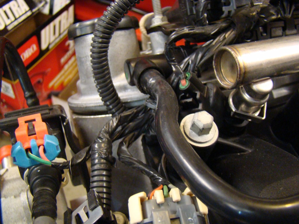
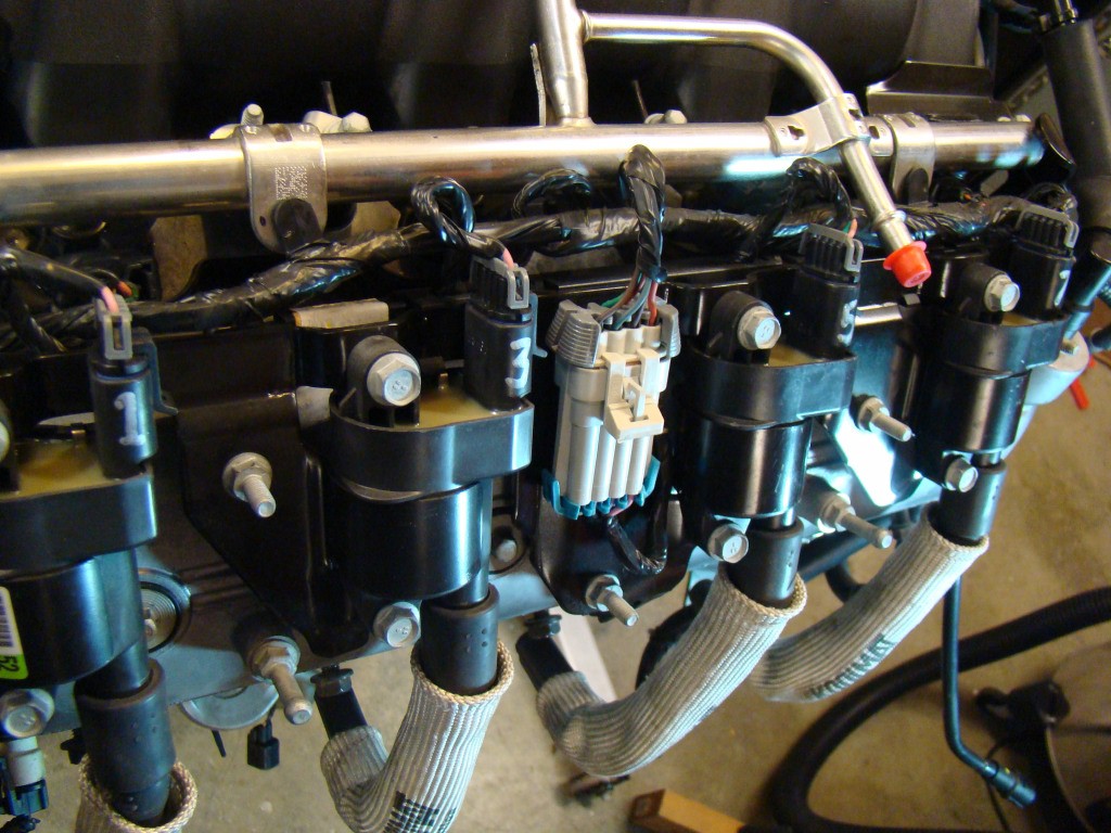
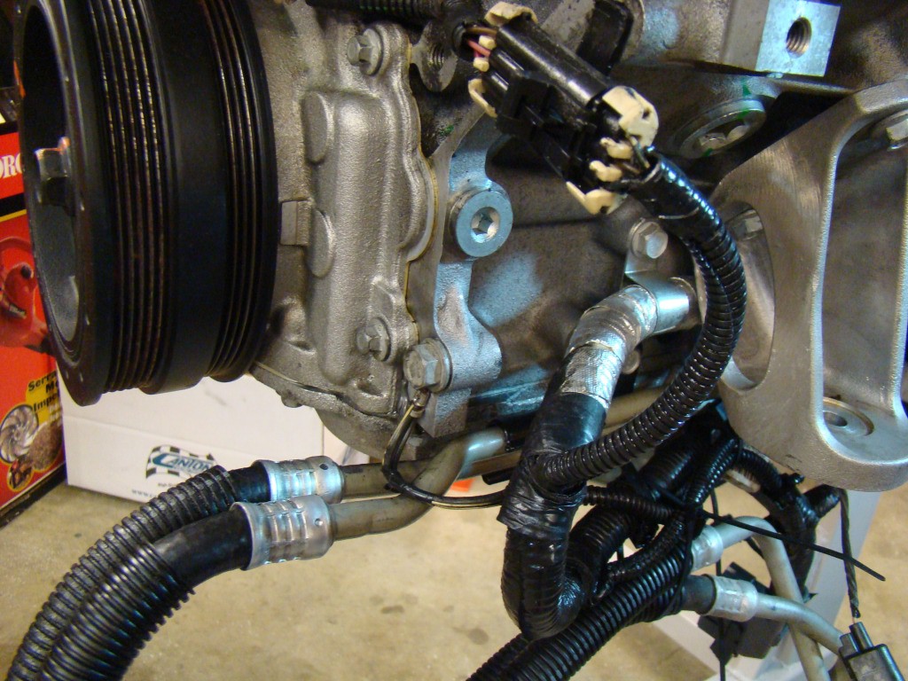
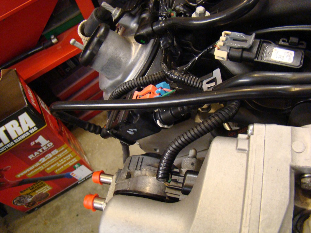
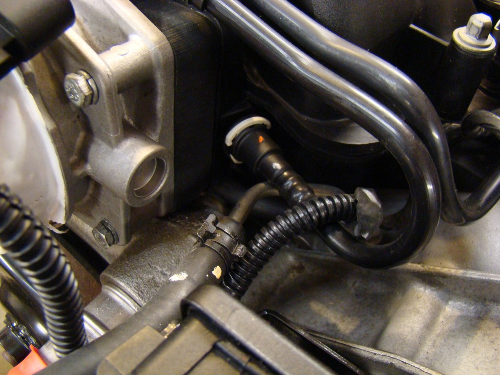
Dissassembly of the upper harness for the injectors and coils is fairly straight forward. I did notice a few things that I know will require some modifications to get everything turned around 180 degrees for placement in the GTM. I'll address those as I can next to the photos.
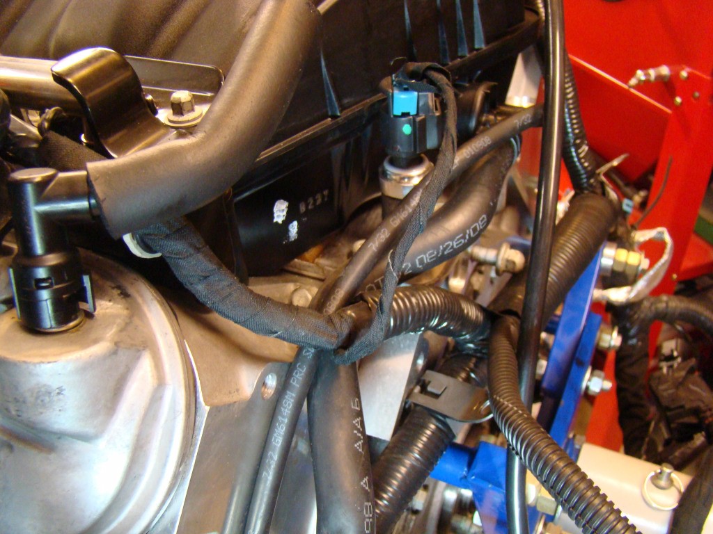
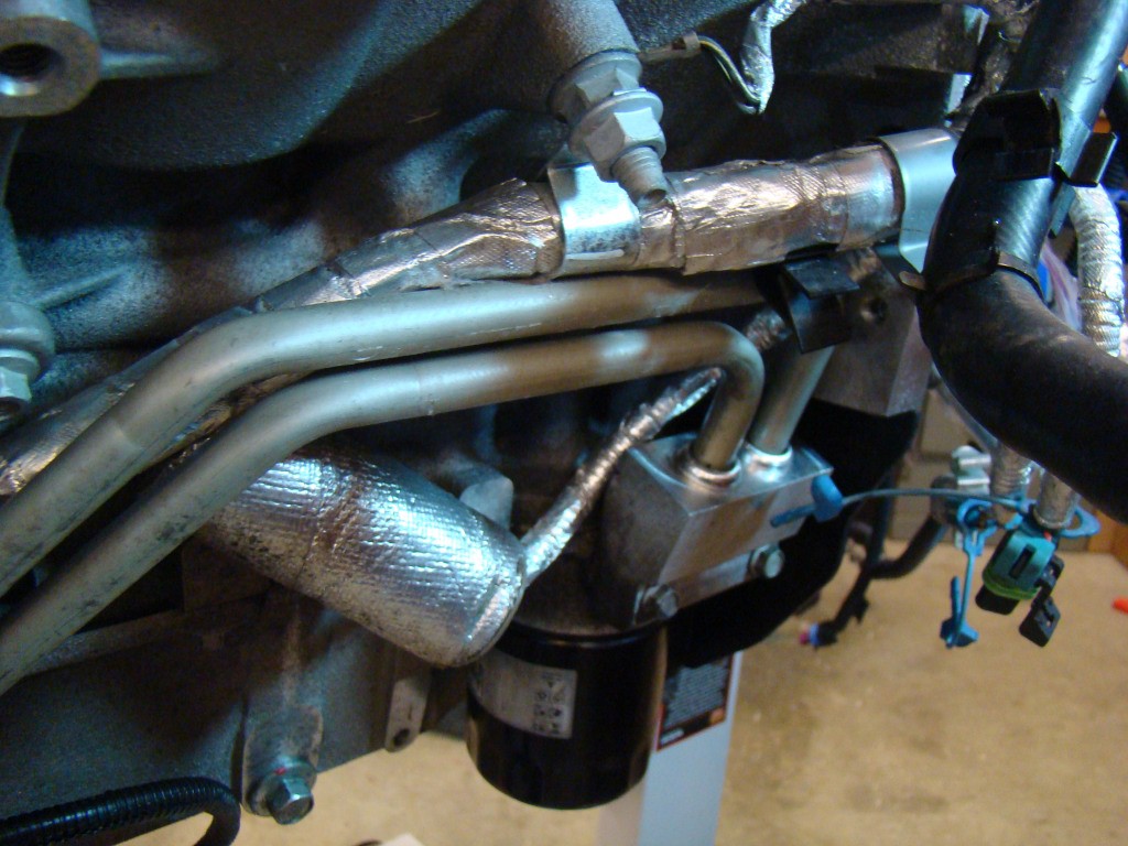
There are a few issues with using the LS7 that need to be taken into account. The PCV system, the Oil cooler setup and the dry sump. I'll walk through the options I used as they occur. I'll need to install the Petersons oil tank and filter tank and then route PCV (Dirty/Clean air)lines between the intake manifold inlet, valley cover and valve covers. I'm currently researching the options for the Oil cooler setup and will likely go with an adapter block and lines that feed the cooler in a custom mounted configuration. We'll see where to put it when the stuff arrives.
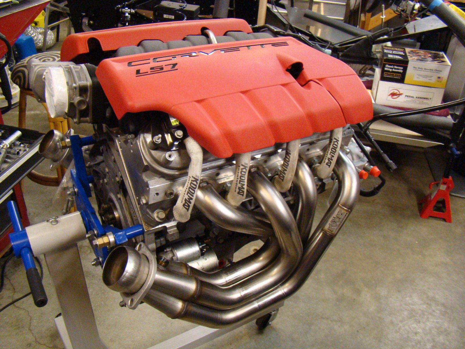
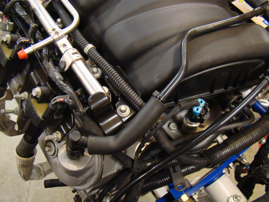
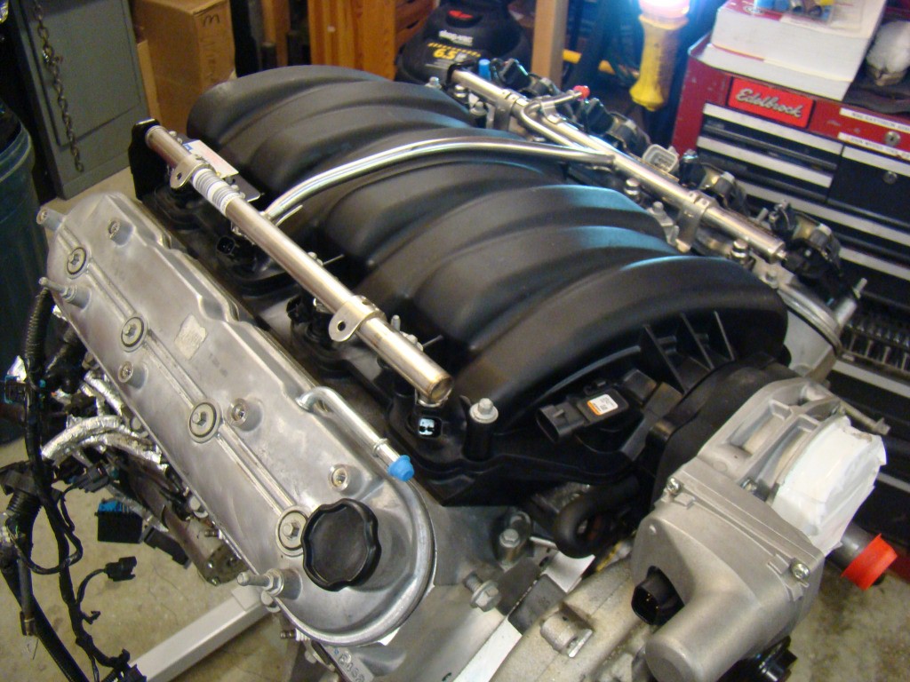
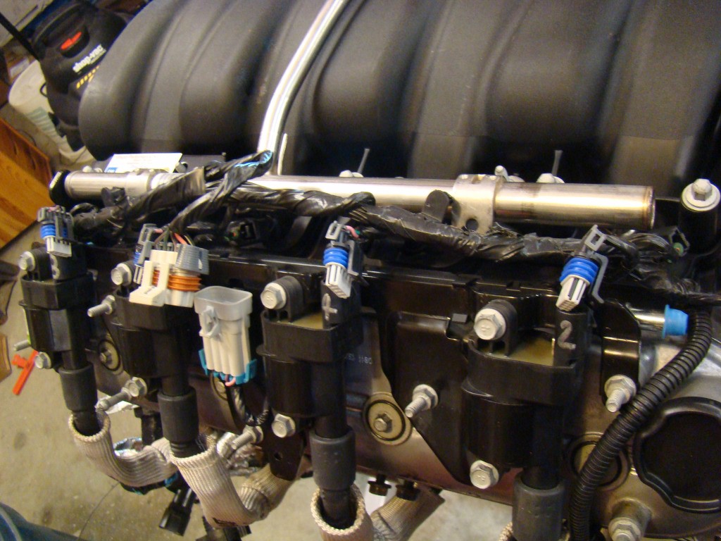
The fuel rail covers actually fit the same in reverse. Even the fuel line inlet lines up with the opening in the cover. It looks nice but I'll likely swap the covers for something more GTM Like.
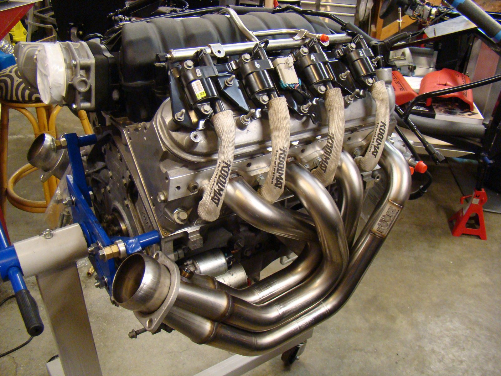
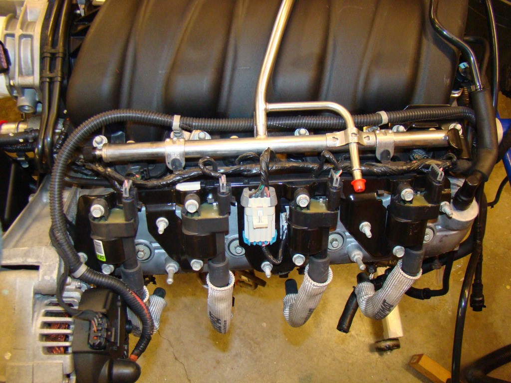
I installed the Coil Packs and decided to add new GM Performance spark plug wires. I had to put the Kooks headers on to see what they looked like.
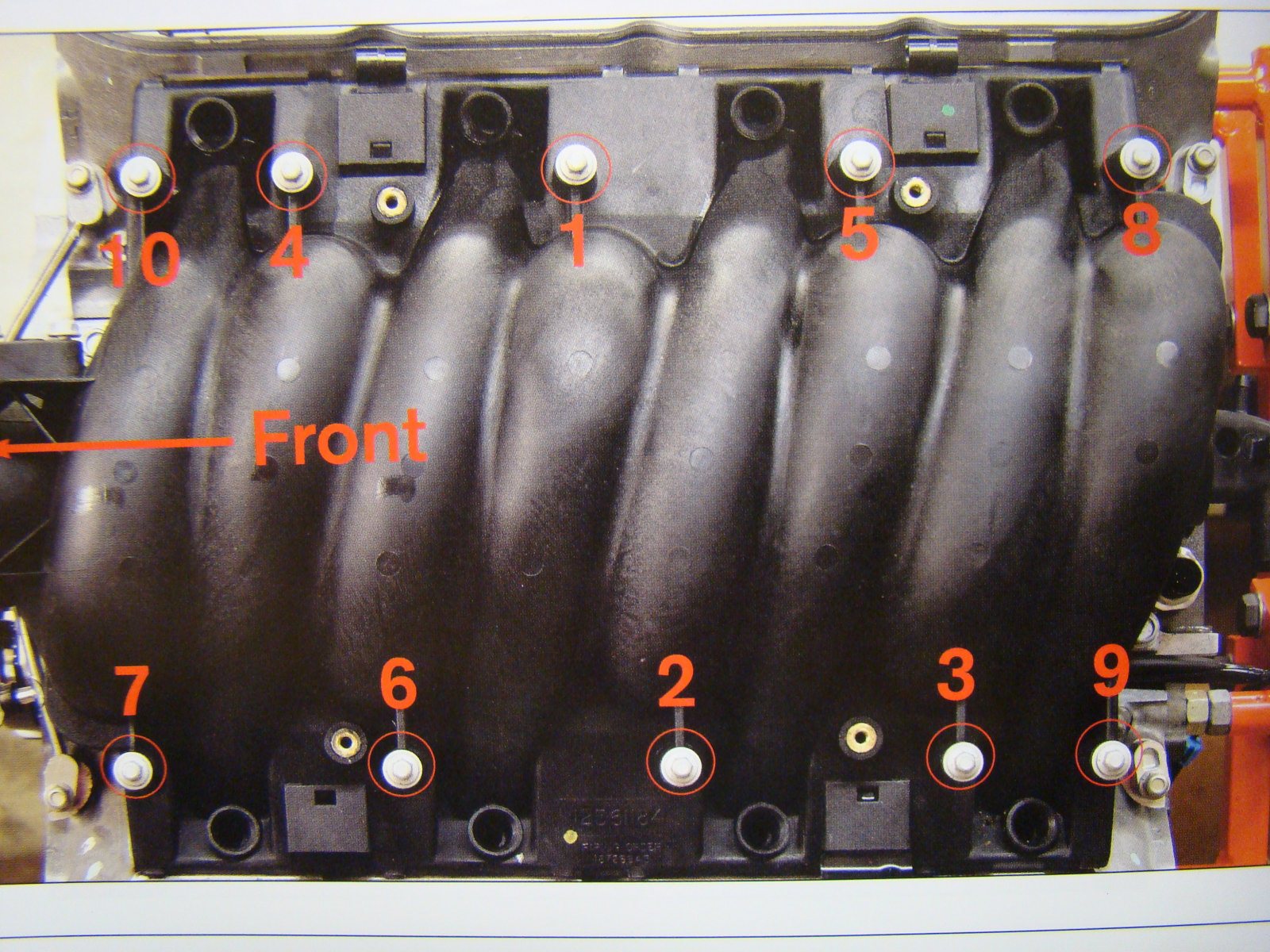
Intake Manifold Torque chart.
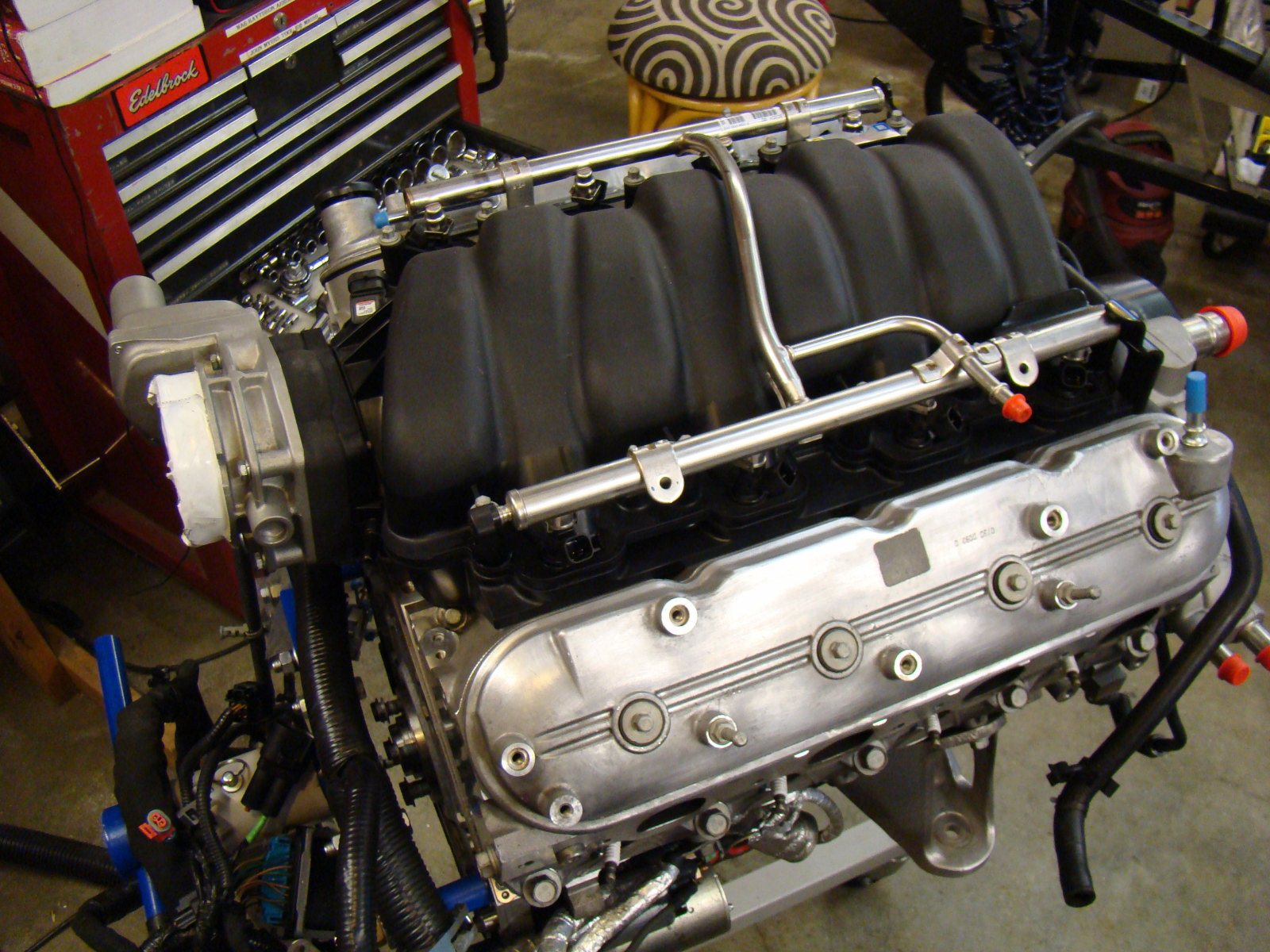
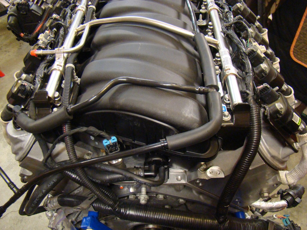
Intake manifold is now in the reversed position and the valve covers have been swapped left to right.
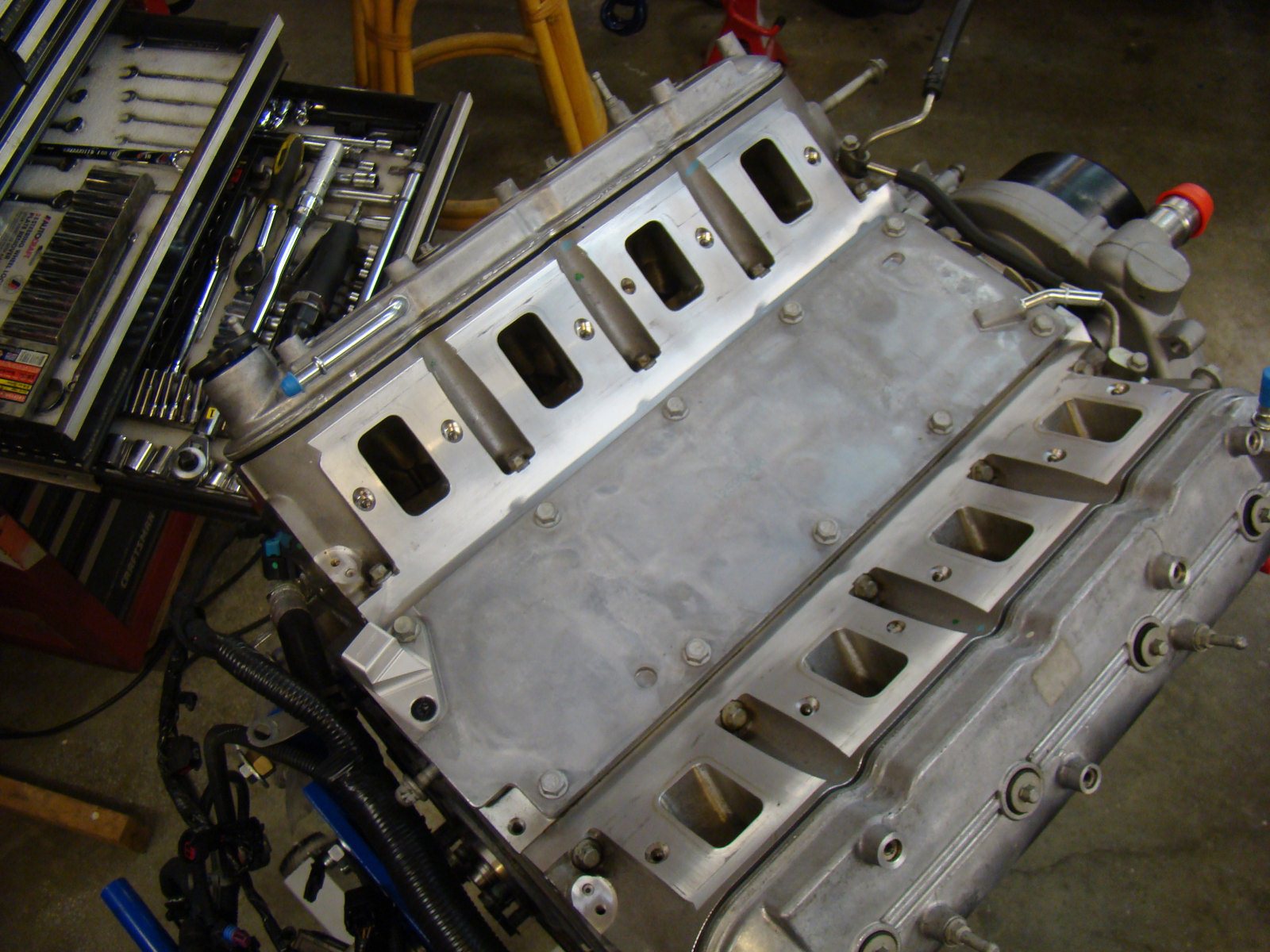
SMC valley cover in place

Removal of the injector and ignition coil wiring harness is simple. Note that you are changing the intake position but don't fool yourself by swapping electrical inputs that run the engine. Cylinder 1 remains cylinder 1 and so the injector and coil inputs should remain the same for all cylinders.
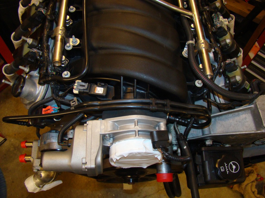
This photo shows the intake still facing forward in the stock position.
Before
diving too deep into the intake reversal you must understand the
peculiar parts needed to complete the job. So far I've
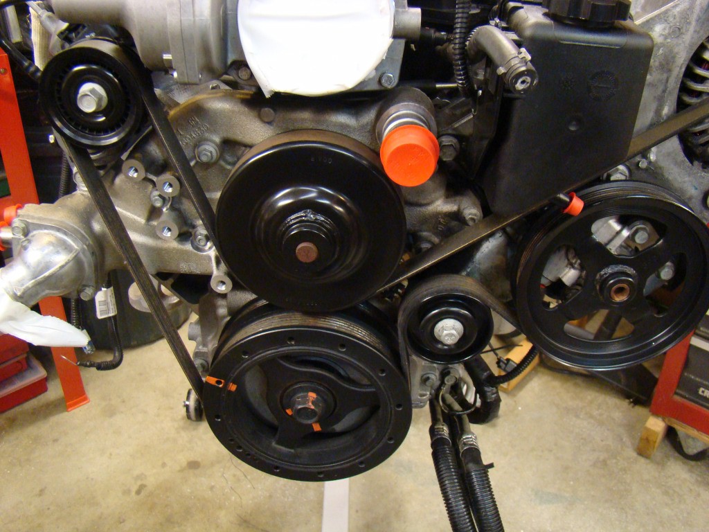
discovered several. The water pump and thermostat housing
housing must be from a 1998 LS1 or like design as shown below. Of
note is the Thermostat housing. The correct one to use is the
one shown on this pump with the extra
tang.
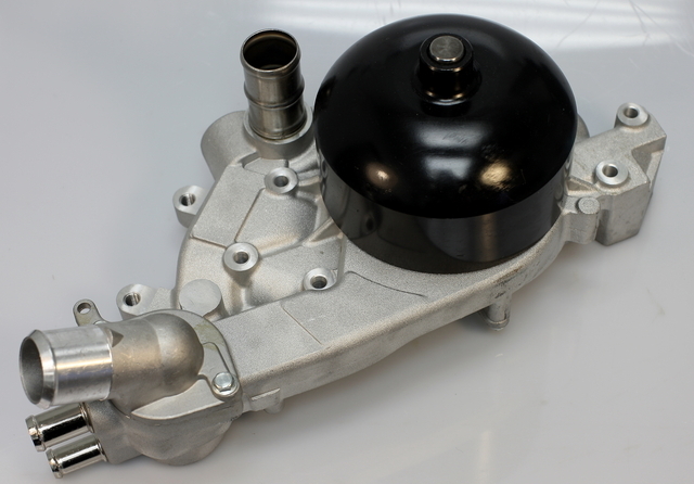
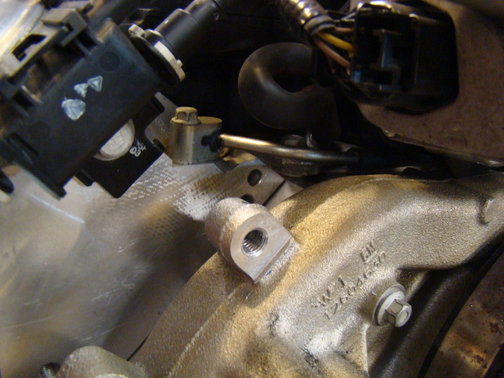
You will find that the LS7 Oil pressure sensor is screwed into
the Valley Cover at the rear of the intake. The threaded
"bung" for the sensor extends upwards to the extent it interferes
with the intake when reversed. To fix this, you will need to
machine the bung down and re-tap or you will need to order an
aftermarket valley cover with the modification. I went with
the setup from SMC performance with the OEM sensor option for the
threads. Guys are using an Autometer pressure sending unit
but I'll wait to see how the setup works with the OEM sensor.
Below are pictures of what the stock and modified parts look
like.
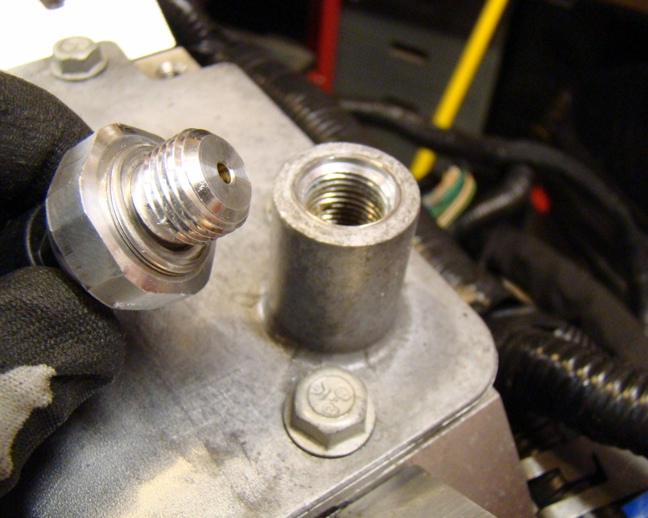
This is the stock
setup
The three photos below show the SMC setup with the cast aluminum 90 deg fitting and modified valley cover. This is what I installed prior to the intake manifold being positioned in place in the above photos.
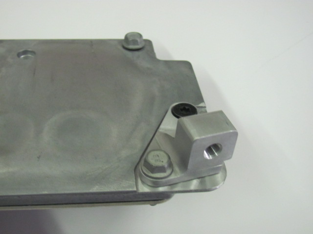
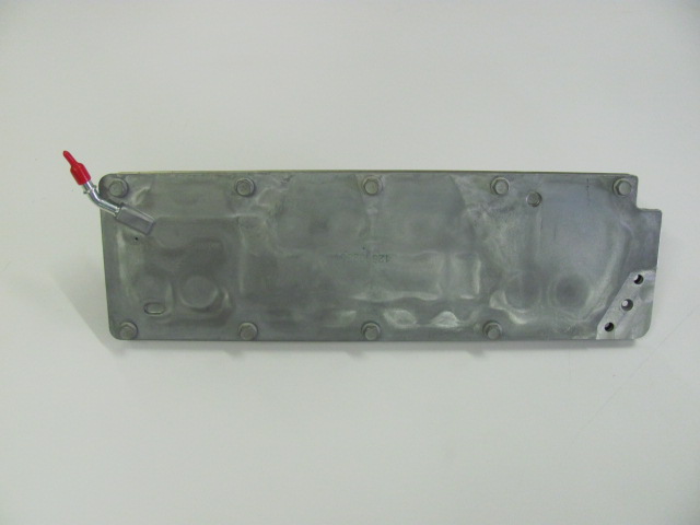
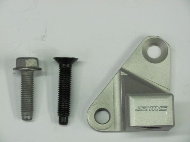
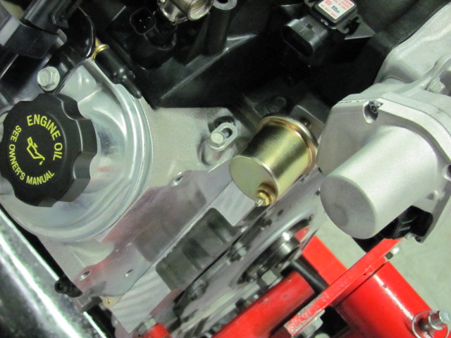
Modified Valley cover with Autometer sending unit
installed
I am a text block. Click on me to drag me around or click a corner handle to resize me. Click the settings icon (it's the left one, looks like a cog) to change this text. You can type new text into me or cut and paste text from somewhere else. Click outside of me when you're done and any changes will be saved.
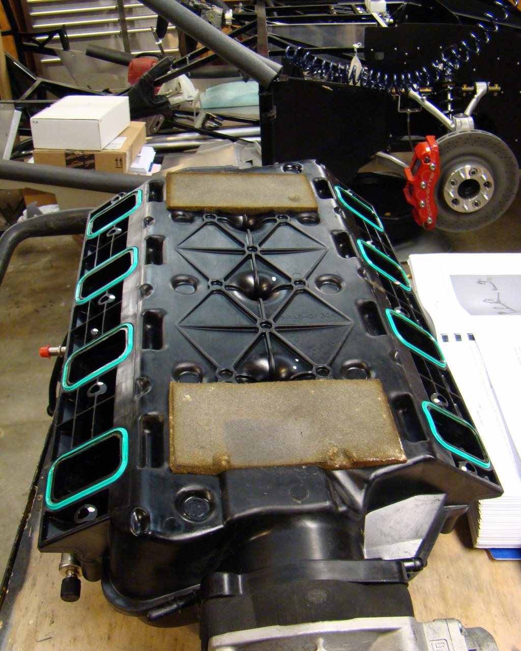
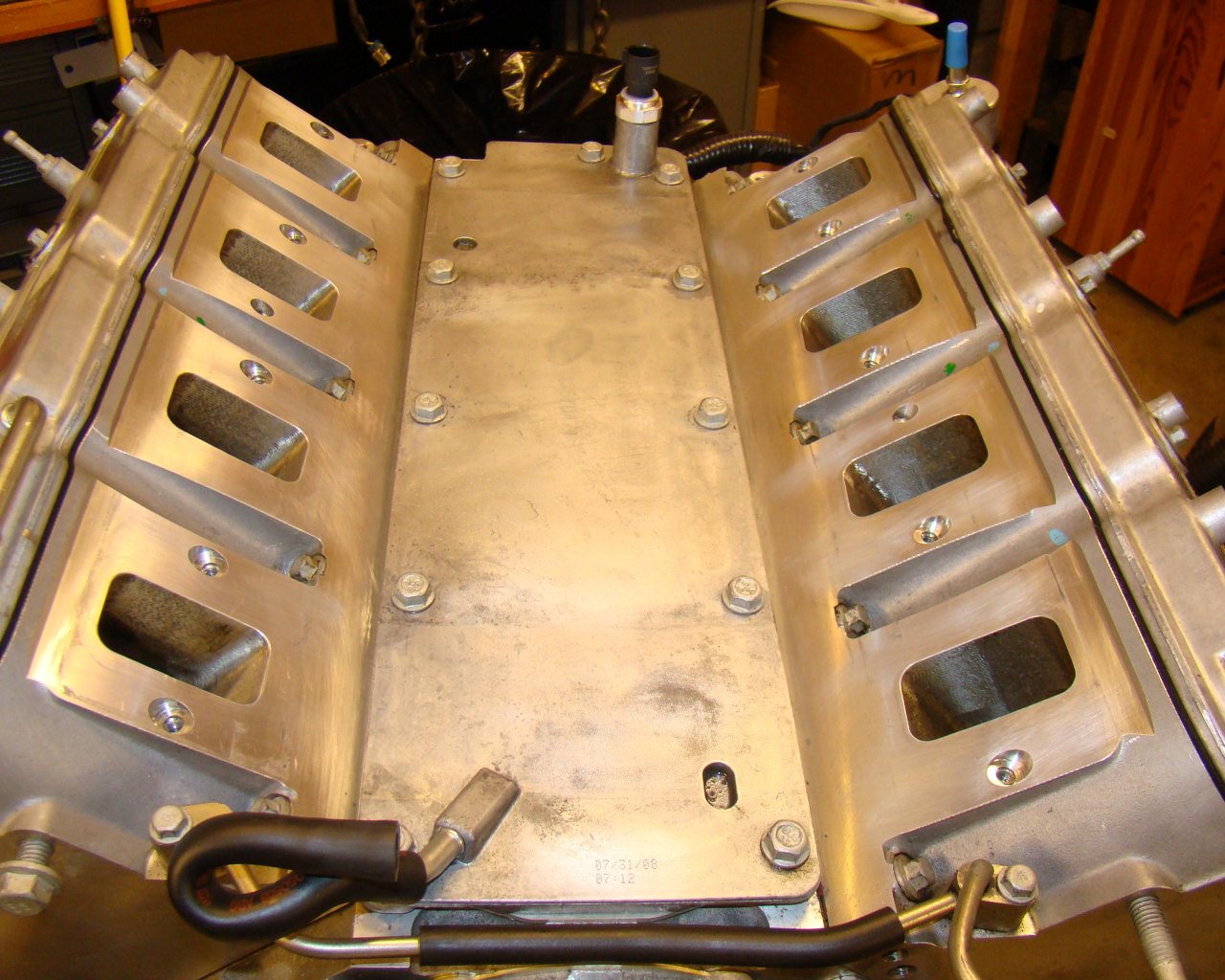
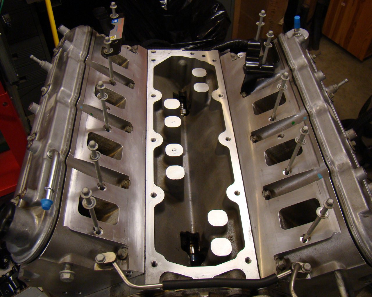
Thats alot of Aluminum. Compared to the older smallblock 350's, the LS blocks are pretty simple. Very symmetrical and everything seems to come apart easily. With Aluminum, it's very important to be careful with fastener torque and removal of stuck bolts so take your time to avoid a major headache that could cost you an engine block. ($$$$$!)
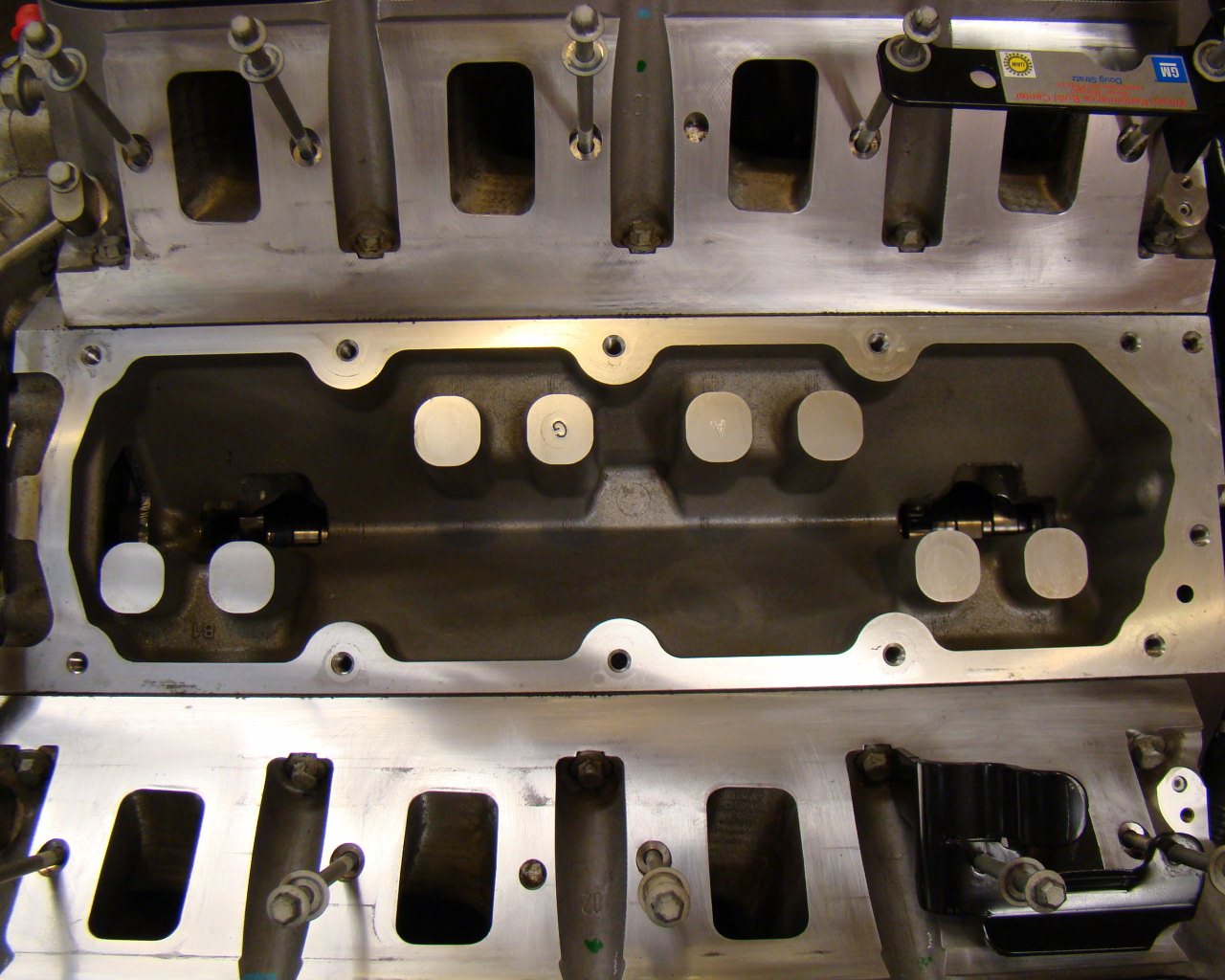
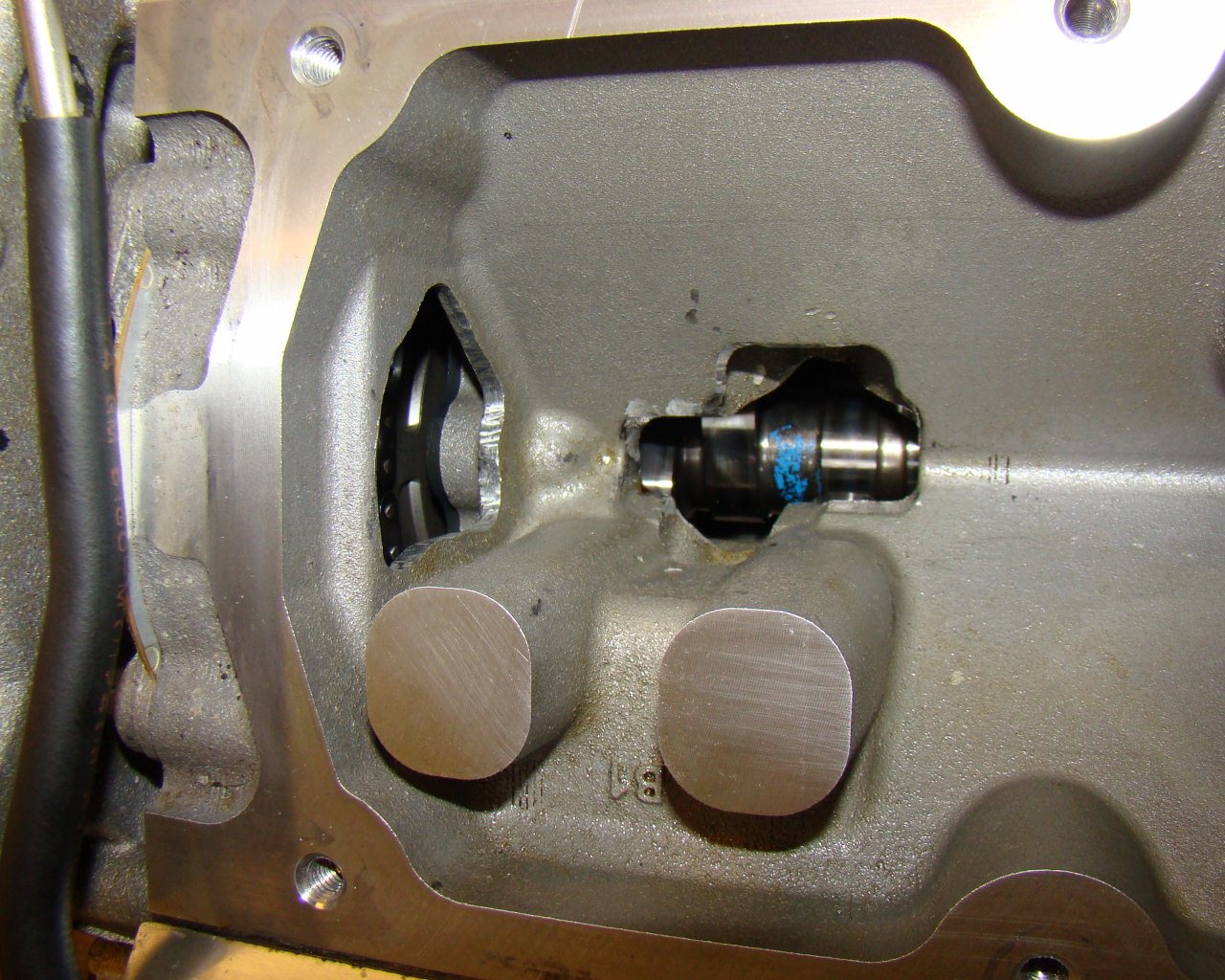
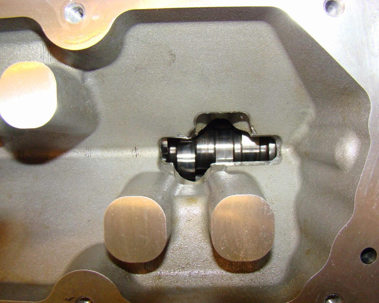
These show the sequence of the Valley cover coming off and what you will see beneath it. Looks like a big bathtub. A little different than the old blocks where you see the pushrods and lifters.
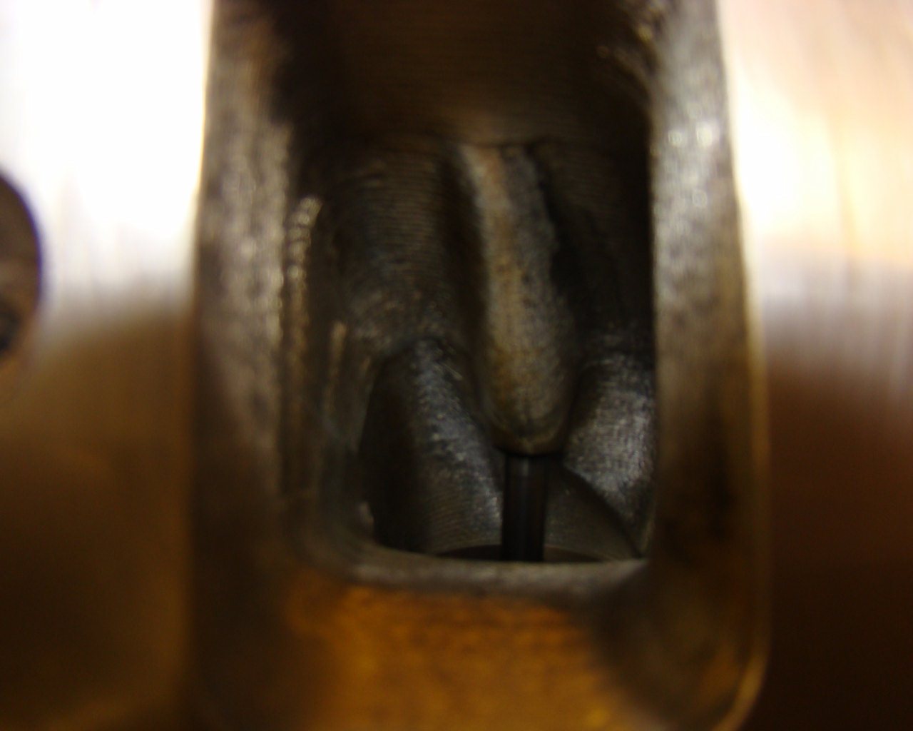
On this motor you can see some of the porting and machine
work. It appears the oil returns were enlarged with a rotary
file. They were definitely not factory casted openings and
whoever did the work was not an artist. It's functional
though.
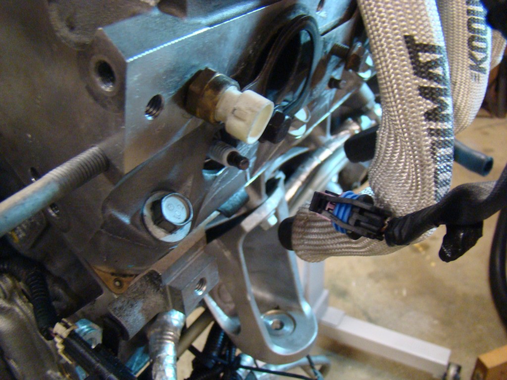
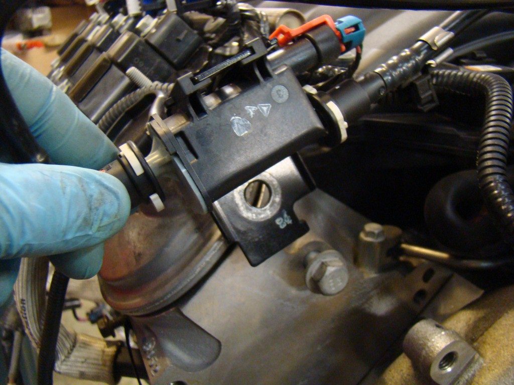
You don't need to mark the coils. Mark the wires going to them
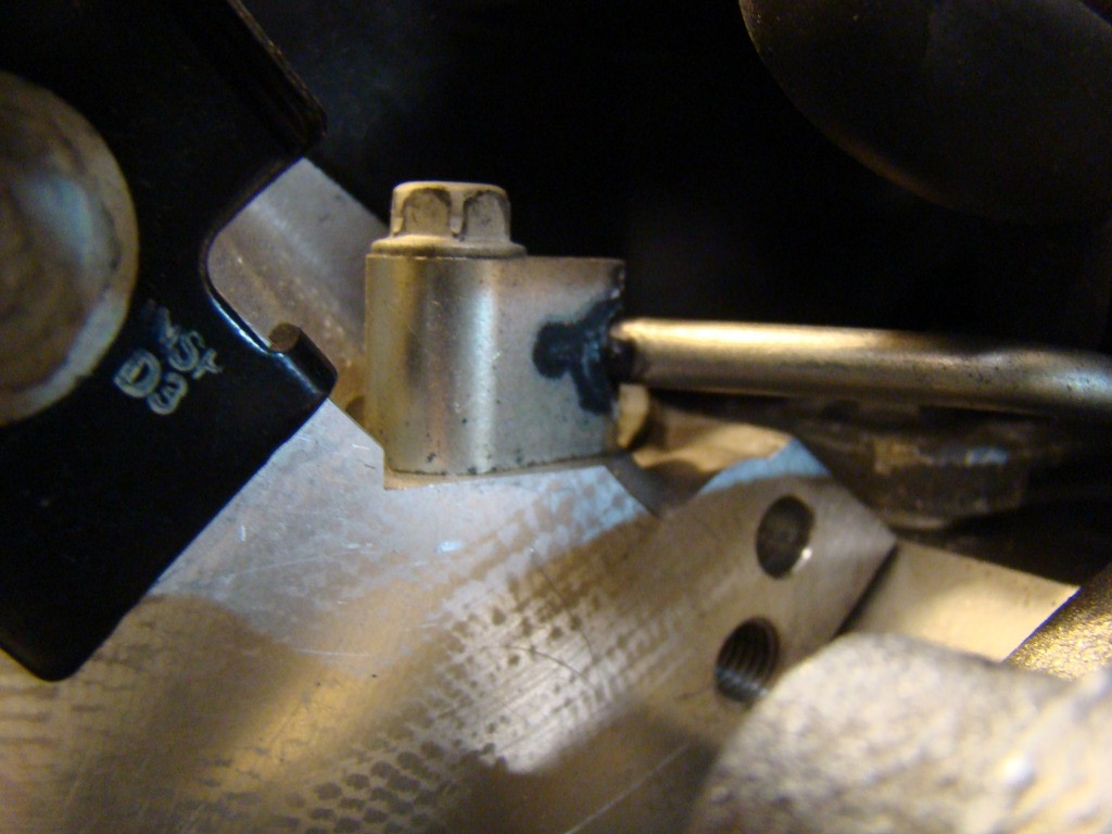
They say that it's critical that you don't block off the head
cooling cross over tube located at the front of the block.
I'll investigate this further as I go to install the intake in it's
new position. There are a set of ports and tapped screw holes
at the aft part of the block in the same locations. It
appears they would make a perfect location to transfer the tube to
the rear where the rubber tube (not shown here) would pick up the
connections to the intake. I'll leave them alone for
now.
