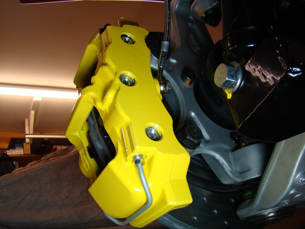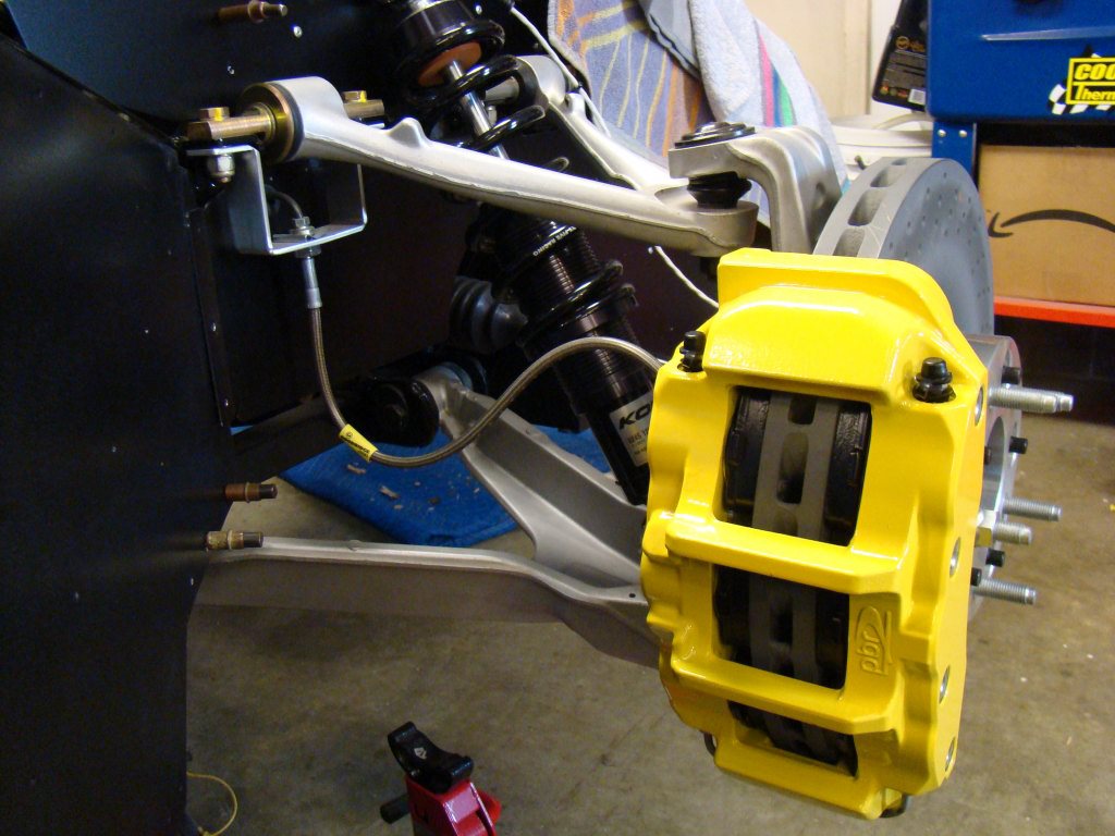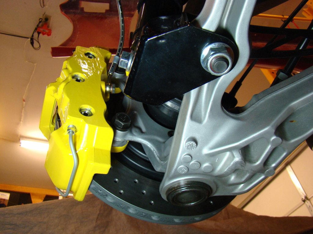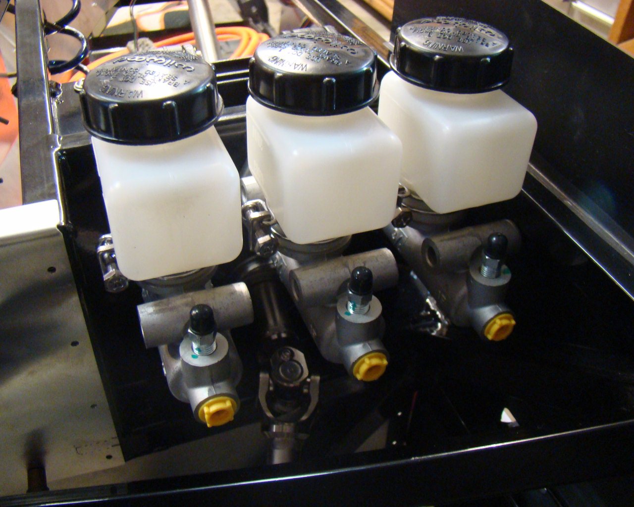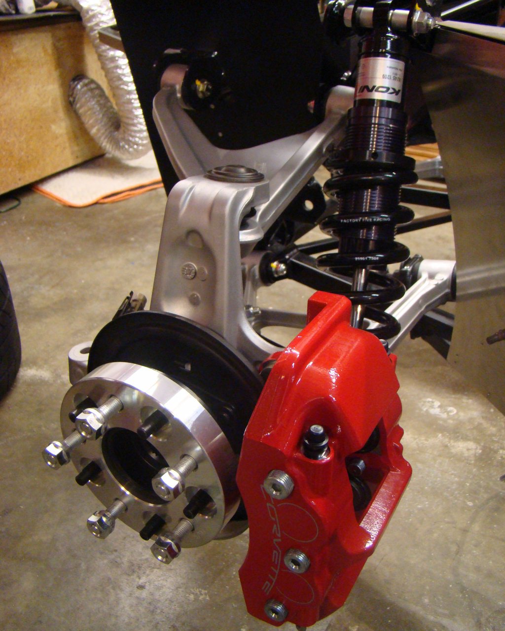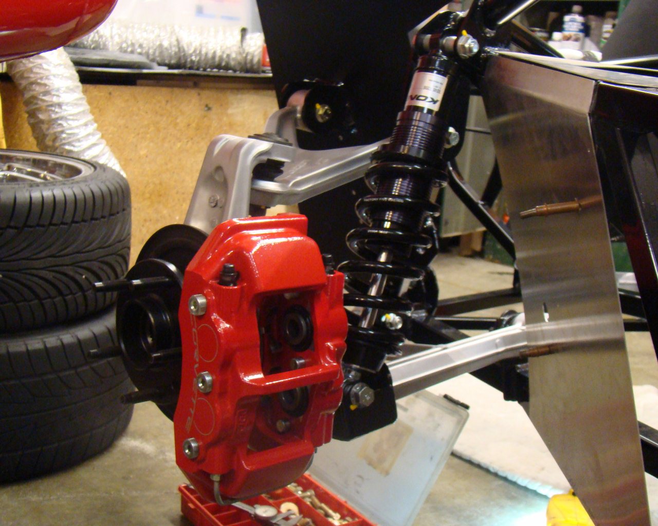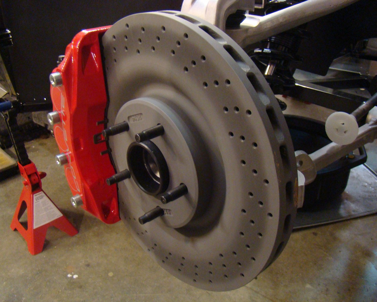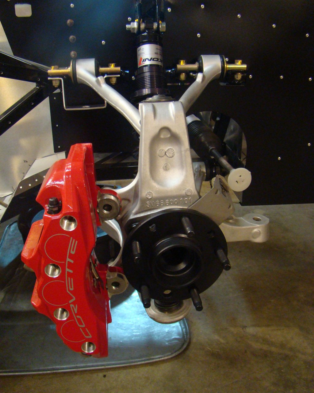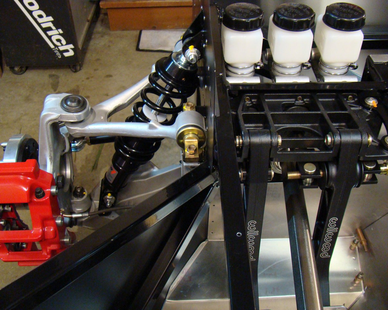
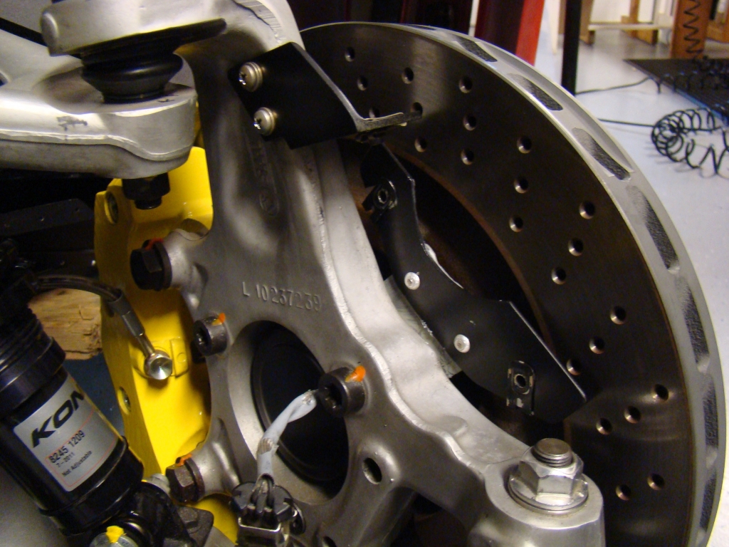
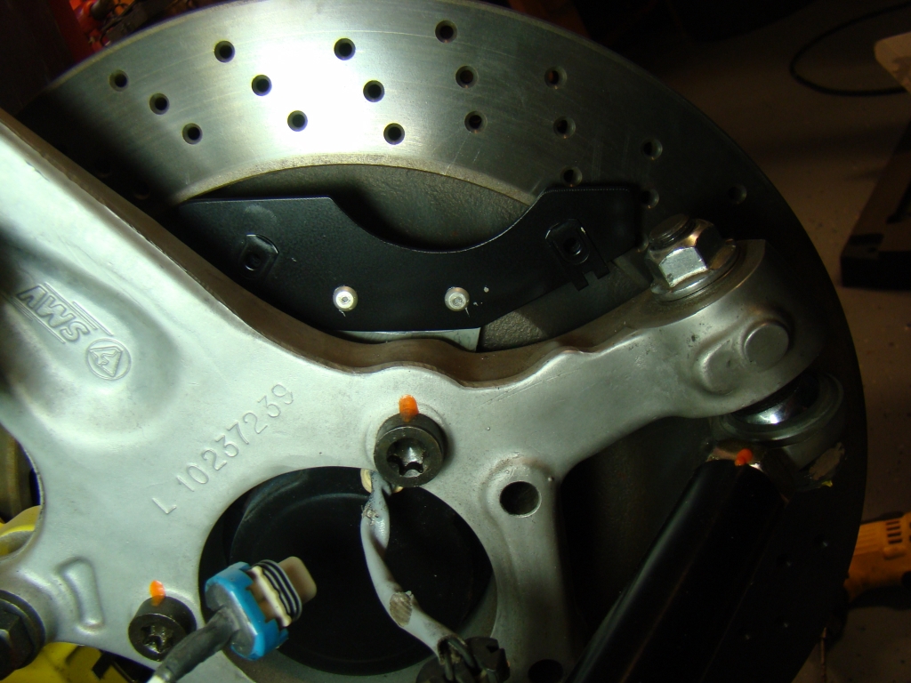
BRAKES
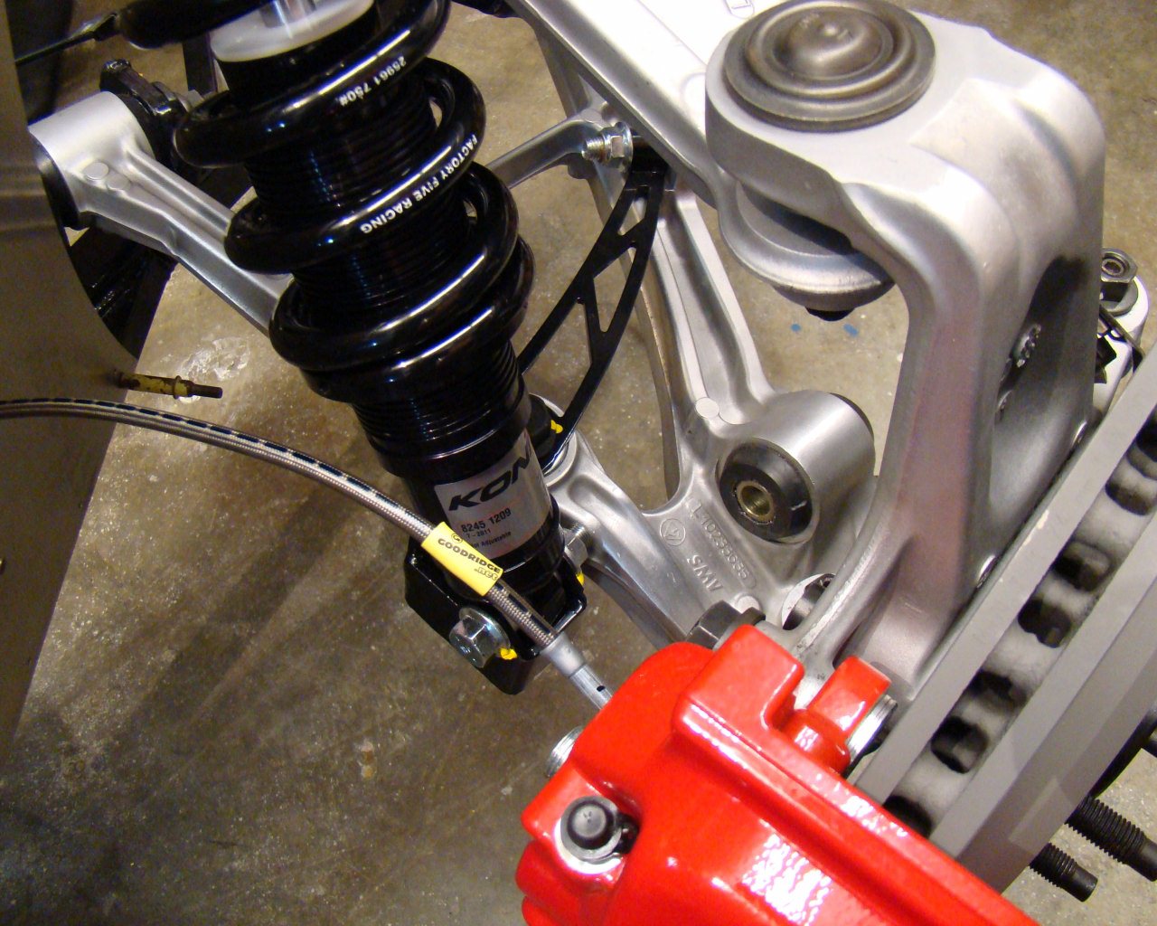
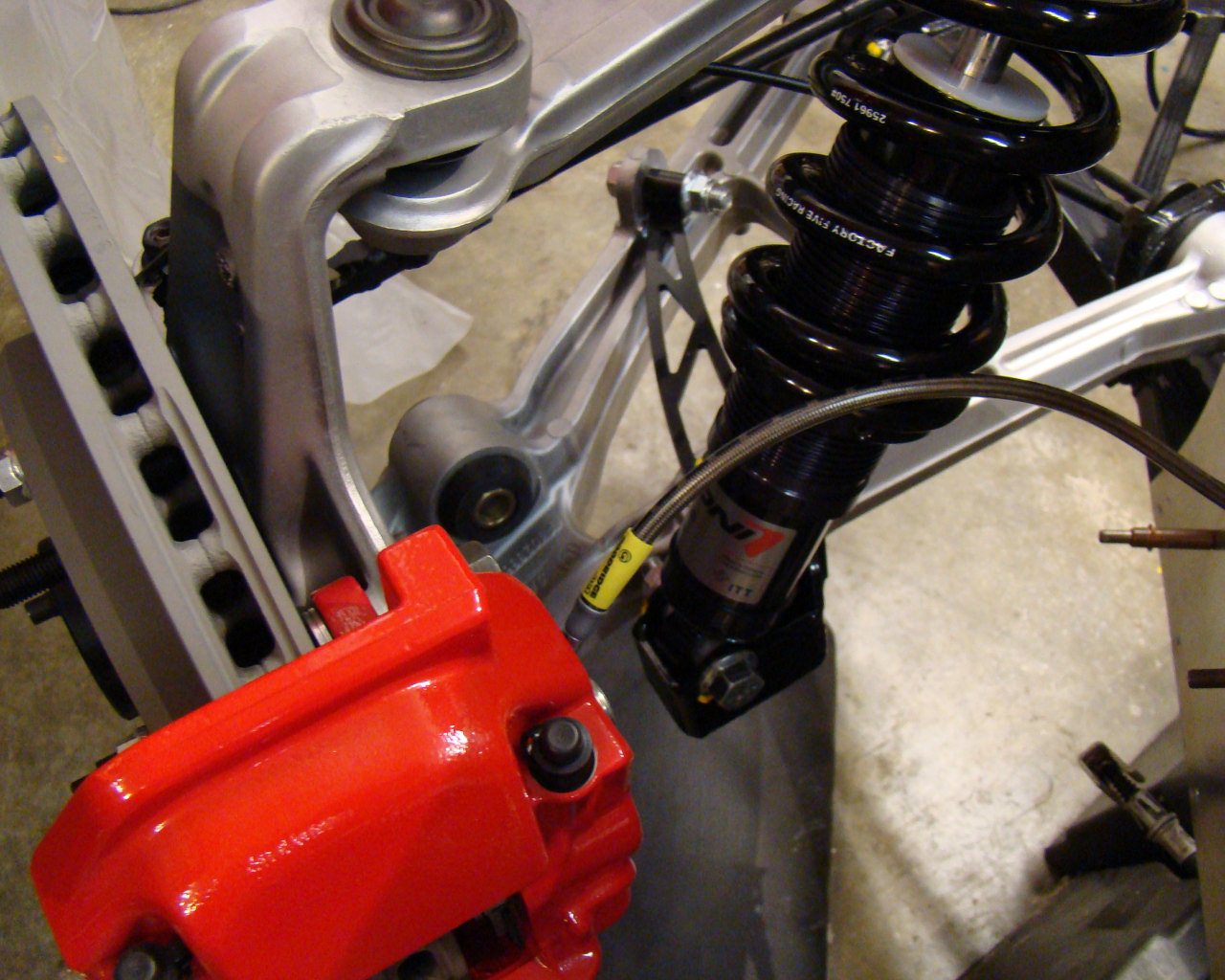
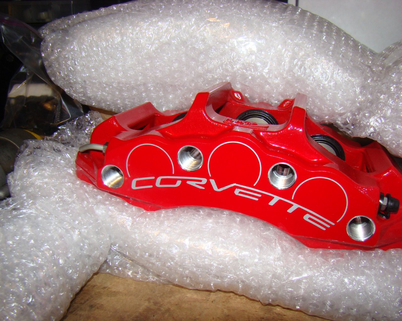
After searching and doing some research on brakes I decided to go with the C6 big brake set. These are what come stock on the Z06 and they are production car proven. I did consider Brembo, Wilwood and Baer but honestly didn't see the need to spend the extra bucks. The Corvette brakes for the Z06 are just as good at stopping the car and there is no guess work involved. The entire package includes 6 piston front, 4 piston rear calipers, 14" rotors and Goodridge brake lines. The only issue I have with the brakes is that the stock GM rotor drilled holes sweep in opposite directions from left to right. This is either a complete oversight or GM decided that production costs mattered more than the difference in performance. They will work, but they are not optimum. I may decide to change them at some point.
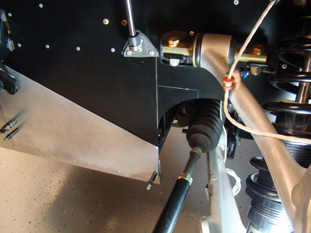
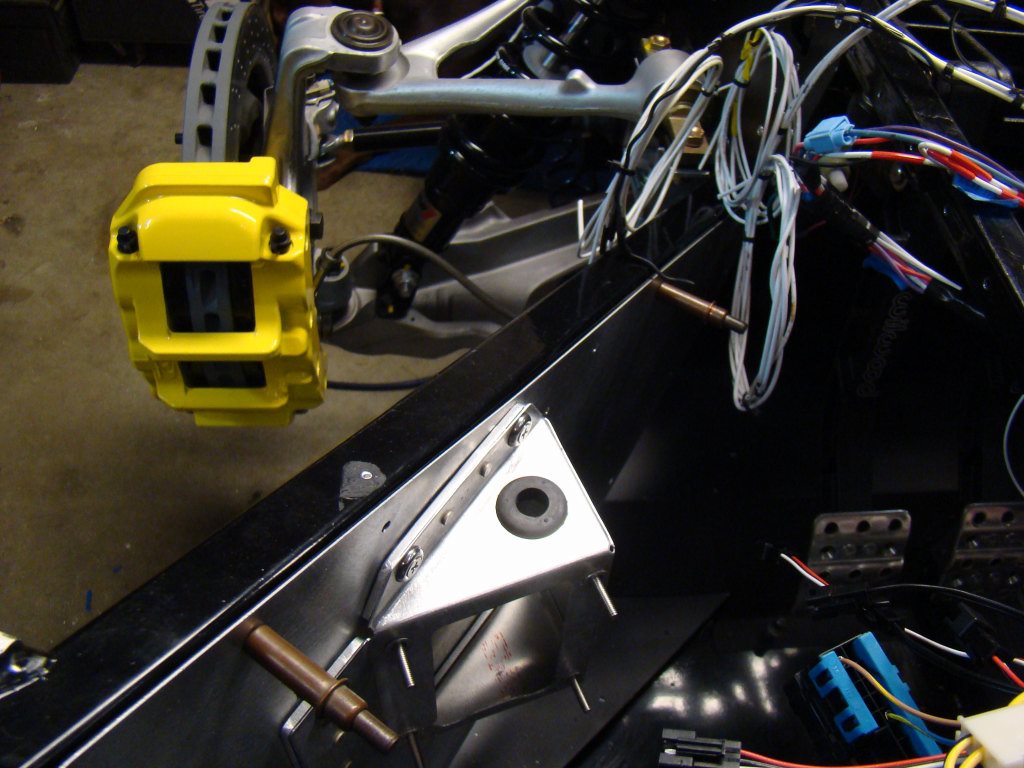
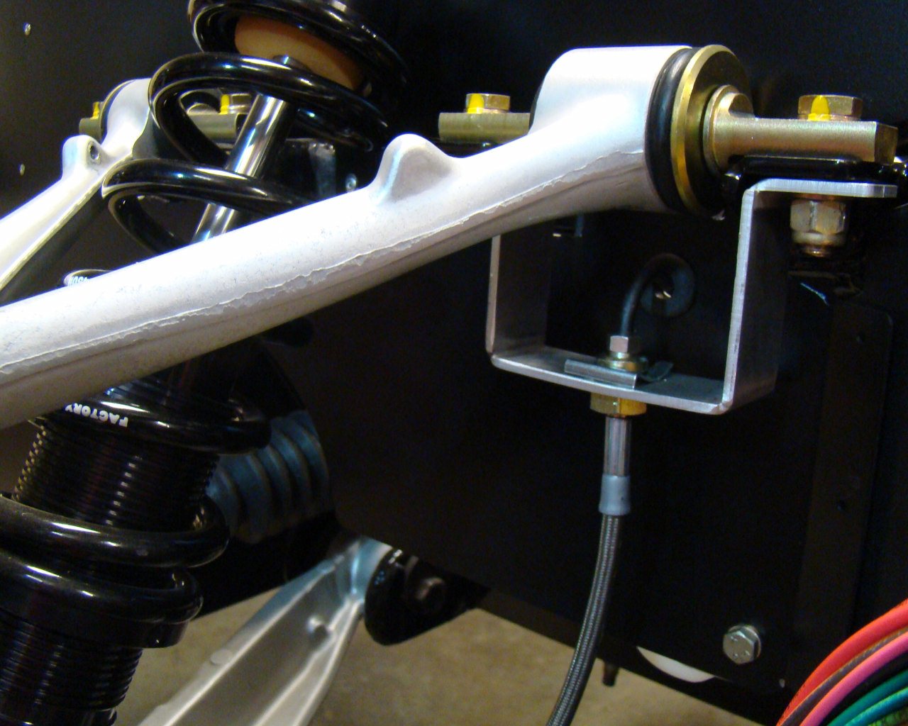
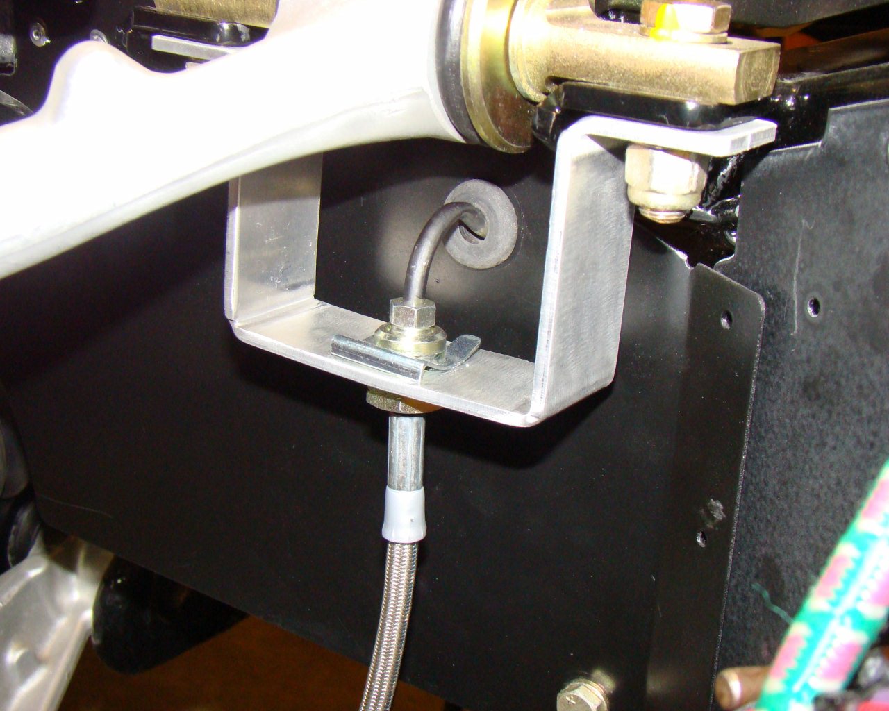
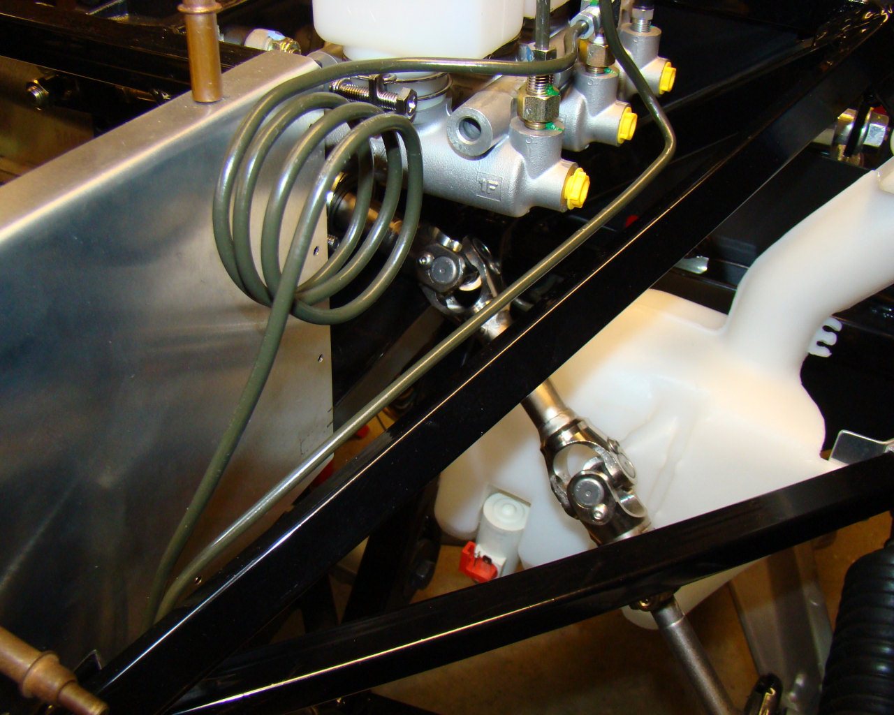
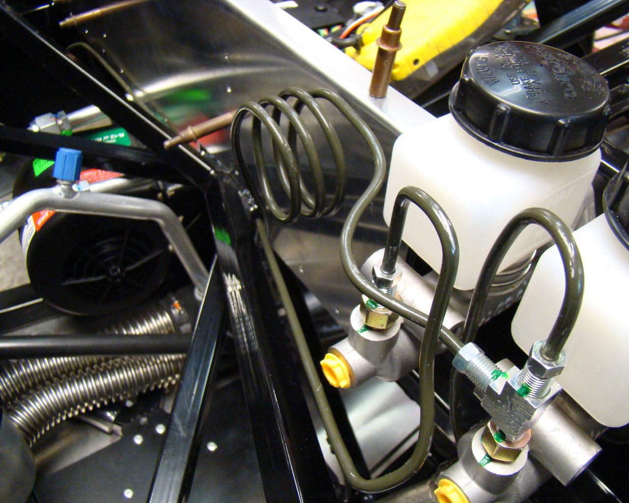
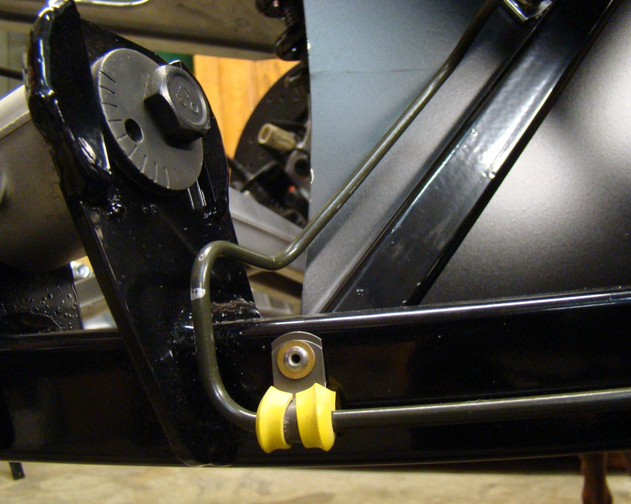
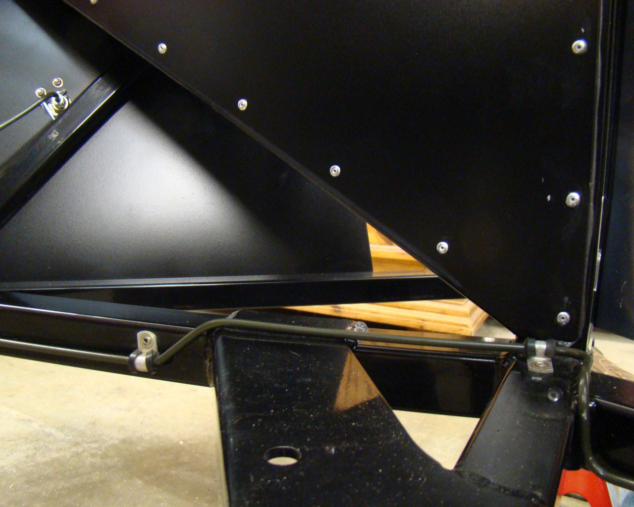
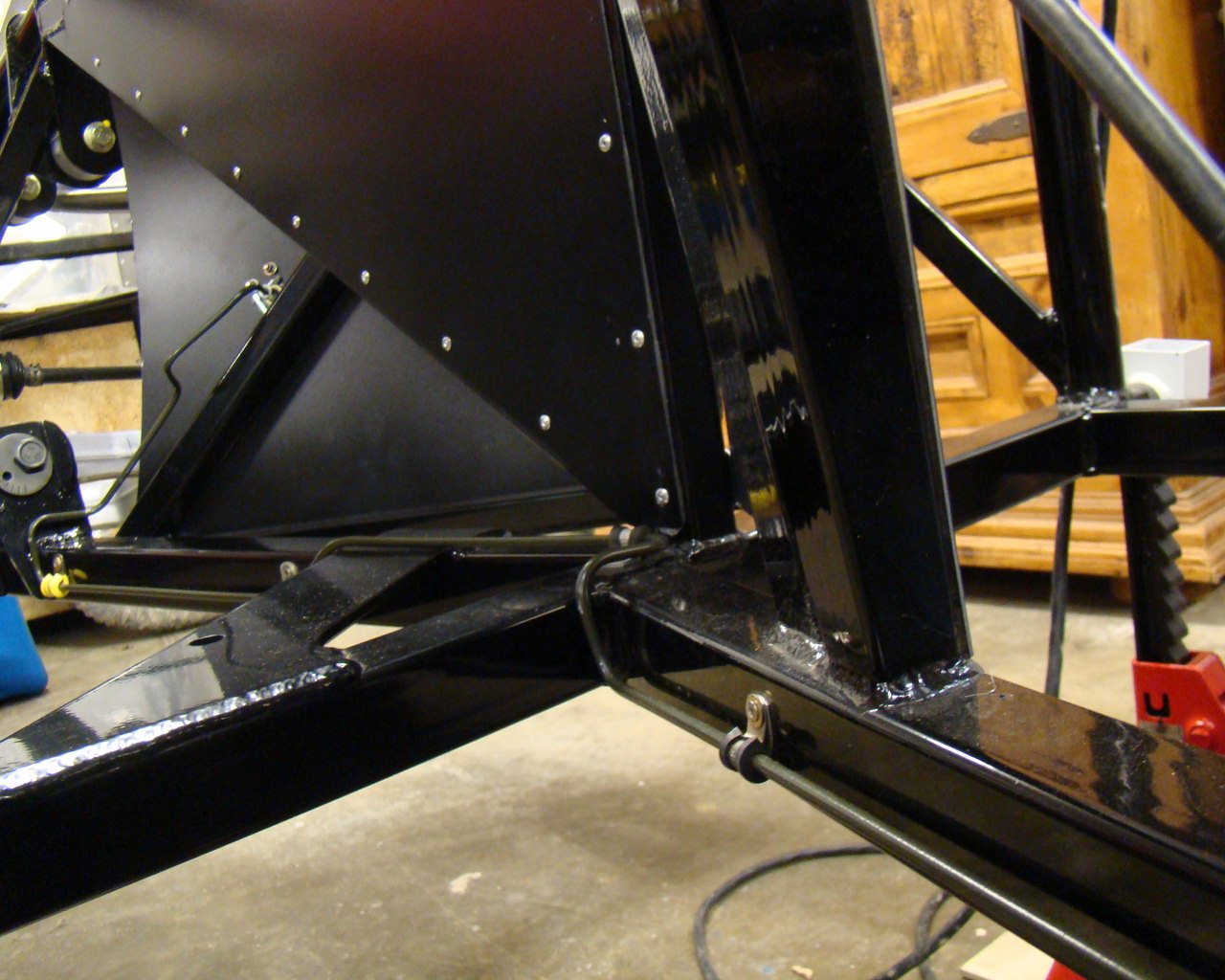
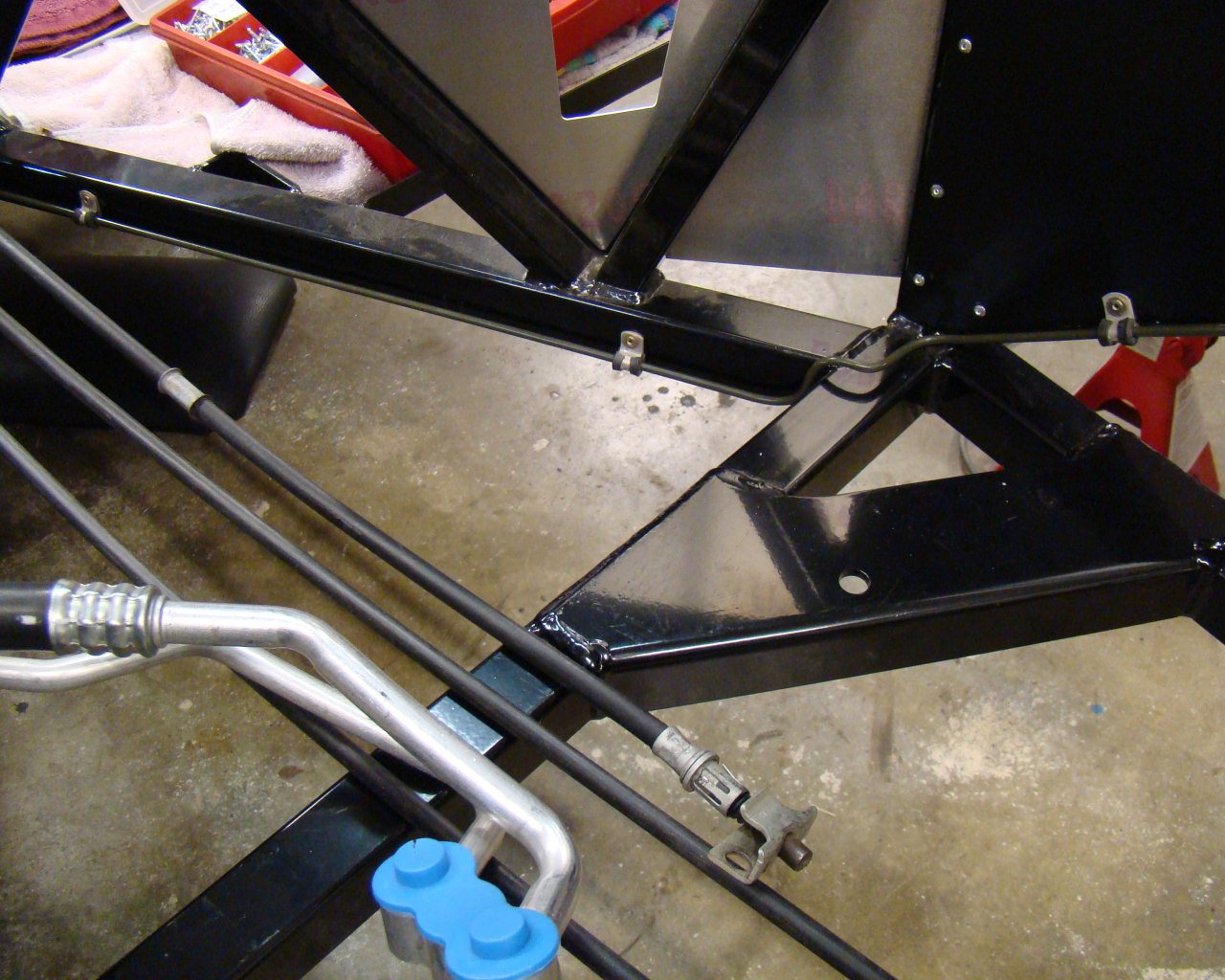
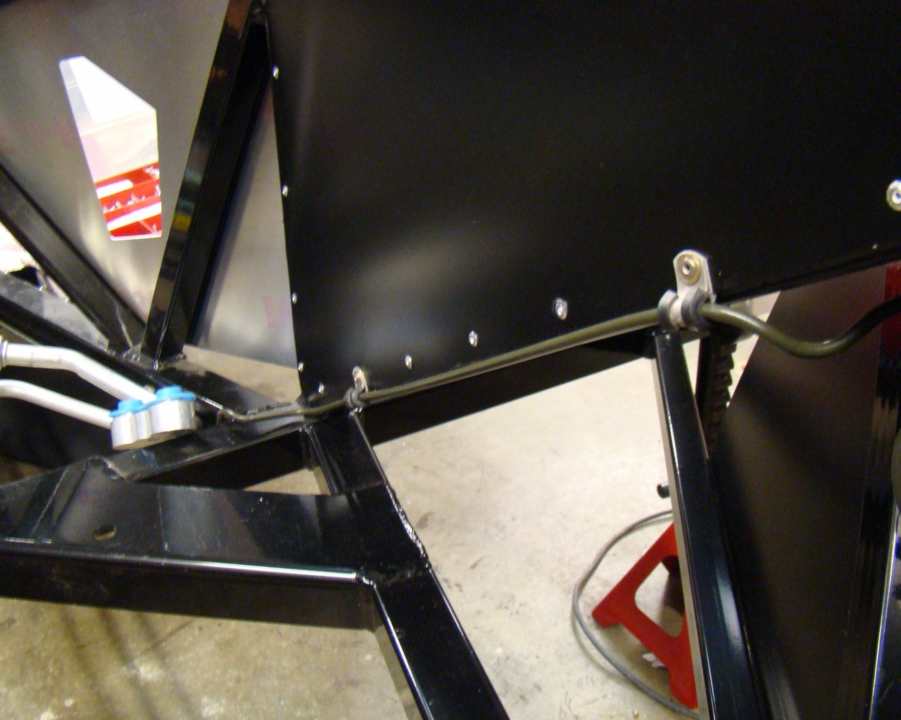
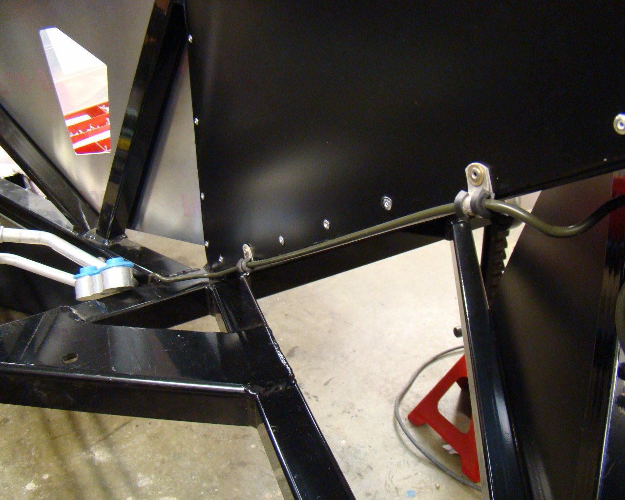
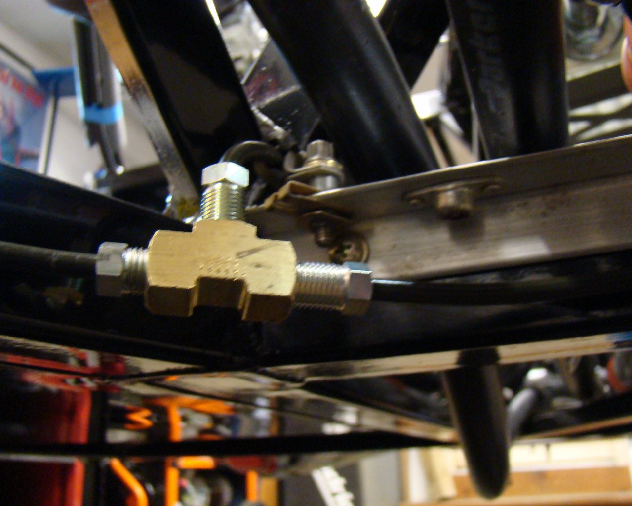
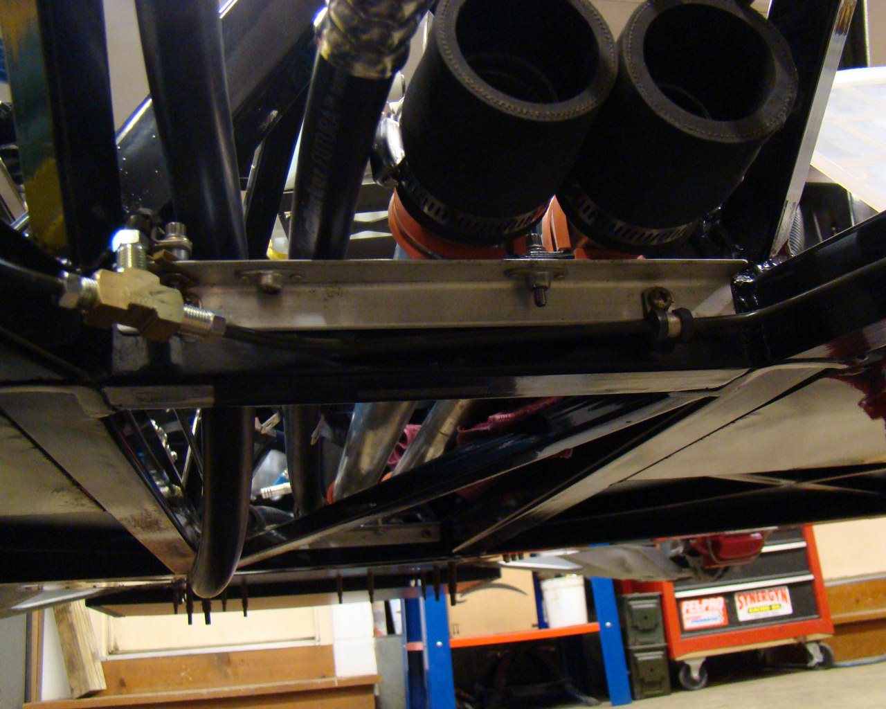
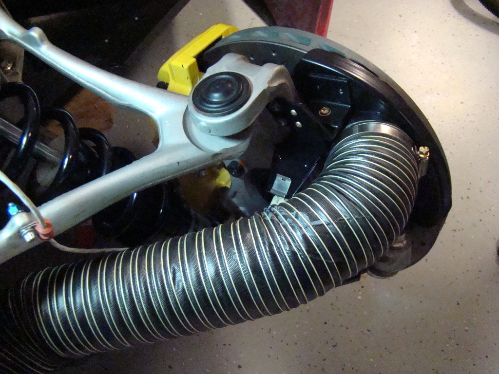
The pictures on the bottom begin with brake line routing.
Bending the lines and achieving the correct path (within clamping
distance of frame members) is not the easiest thing to do.
Starting with a 60 - 80" line makes it very difficult to manipulate
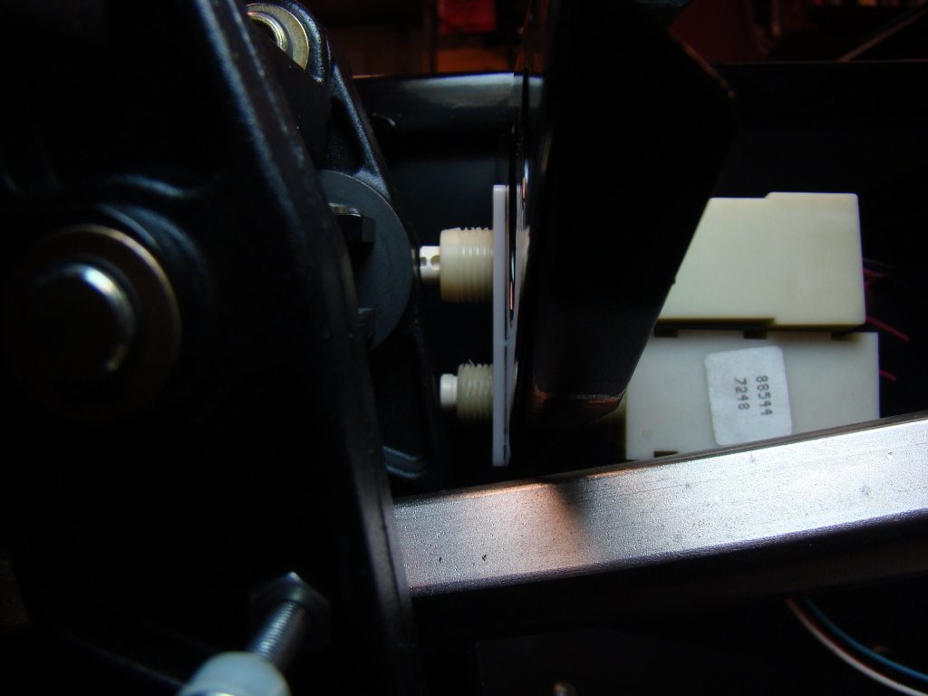
within the working areas. In many cases you will need to
measure and make bends further down the line to complete the bends
around and along frame members long before you actually get to the
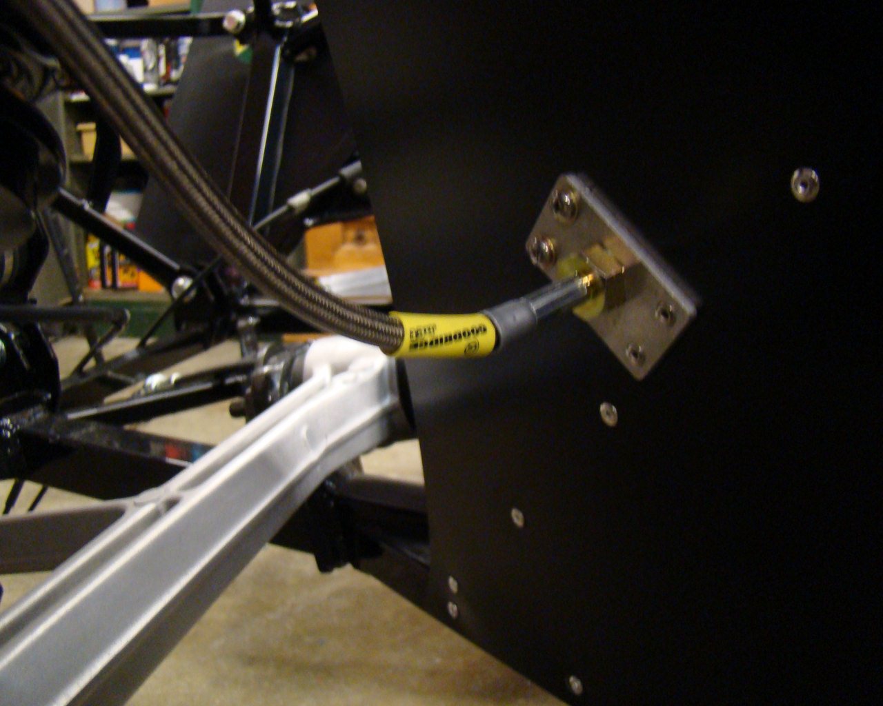
ends. Also, the last bends at the front wheels are
challenging but small radii are possible using a tubing
bender. Various tools, pieces of wood, screw drivers and
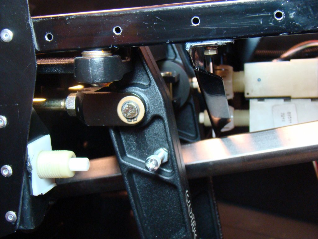
whatever else you can use to assist will be needed. Your
fingers alone won't hold up and the tubing gets stiff when you have
bends in close proximity to
one-another.
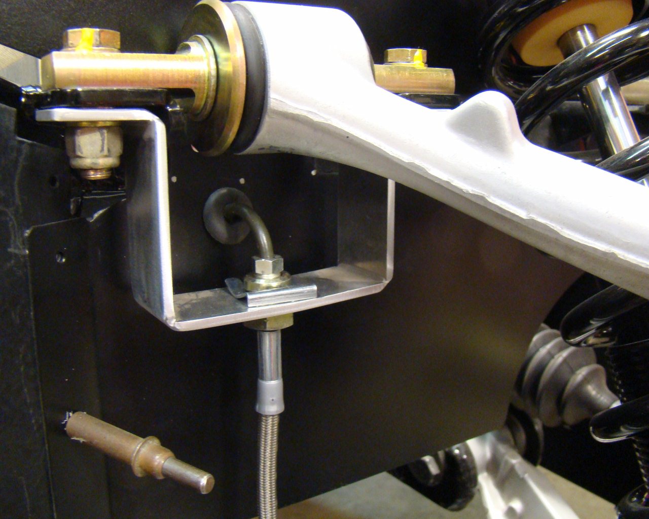
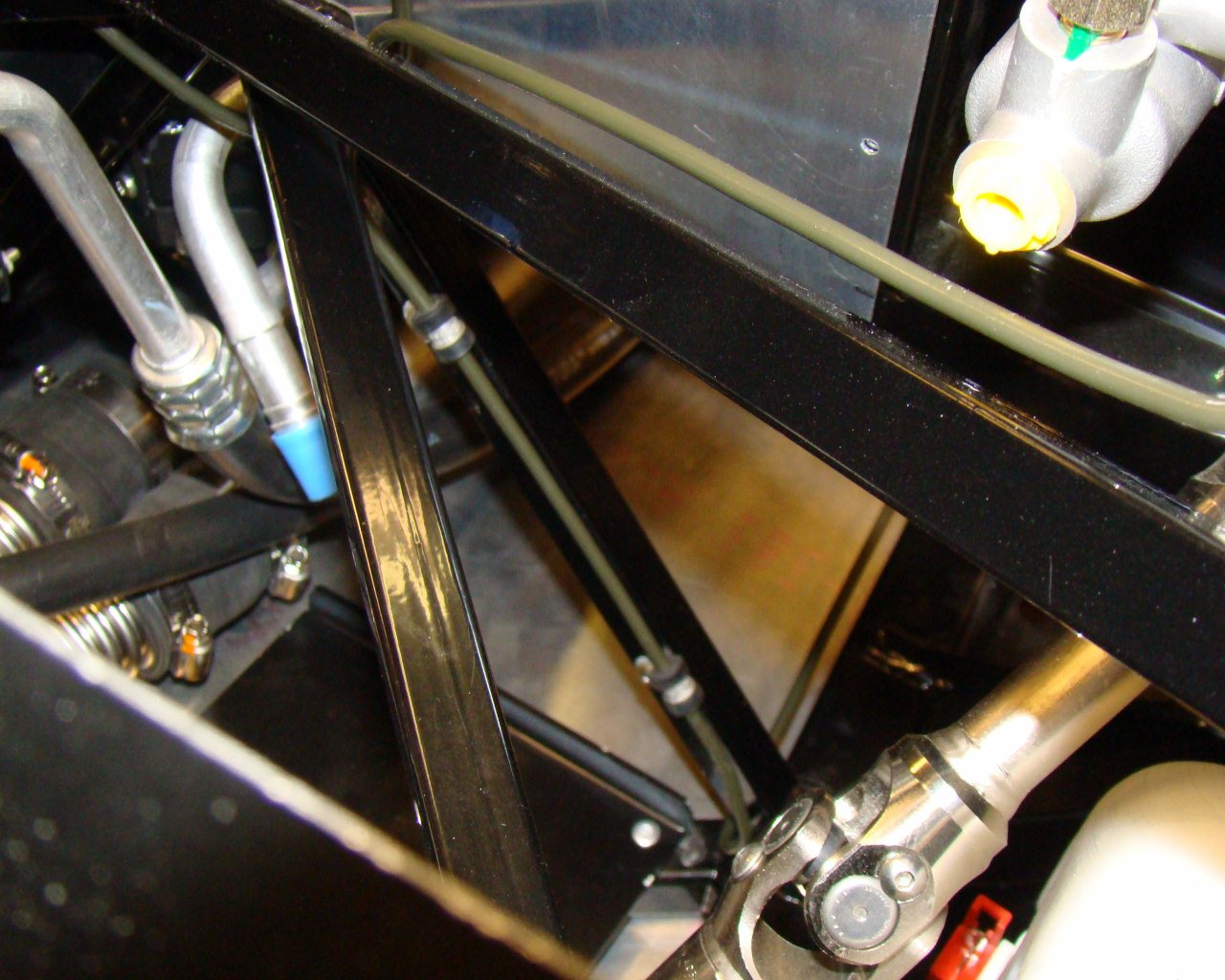
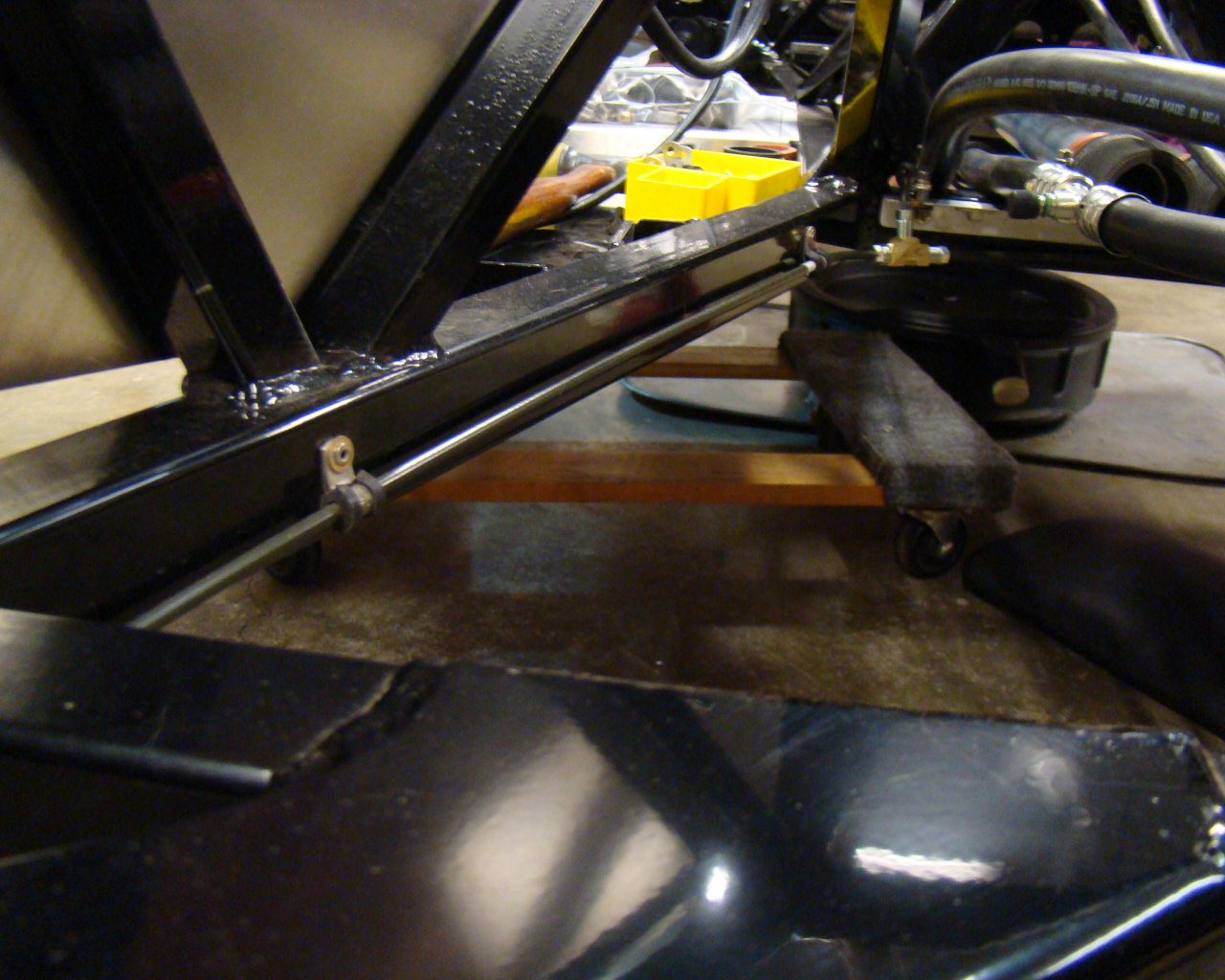
Full
left
Centered
Full
Right
To
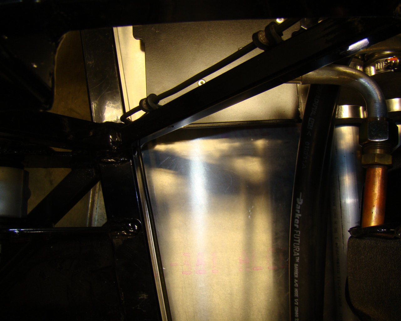
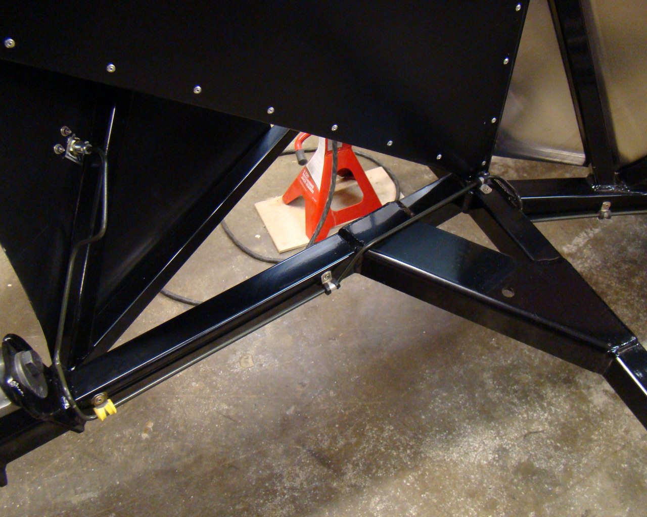
neaten things up I used a piece of the door seal (The FFR seals
separate between the bulb and the part that attaches onto the sheet
metal edge pretty easy. All that time I spent cutting the
radiator box upper seals (the ones under the hood) and they end up
falling apart after resting my arm on them for a few hours off and
on. I noticed this while doing the doors but the one on under the
hood separated along a two foot section. So...I used the
donor Corvette door seals instead). The piece you see is what I cut
off the FFR seal.
There was easy access to the outside
so I used MS20427 4-2 rivets the old fashioned way. A rivet
gun and bucking bar. Note the lower radiator box closeout
incorporated into the doubler and aft radiator box sheet metal
wall. I didn't need the entire corner cutout quite as big as
what I covered with the doubler. Only the radiused area is
needed.
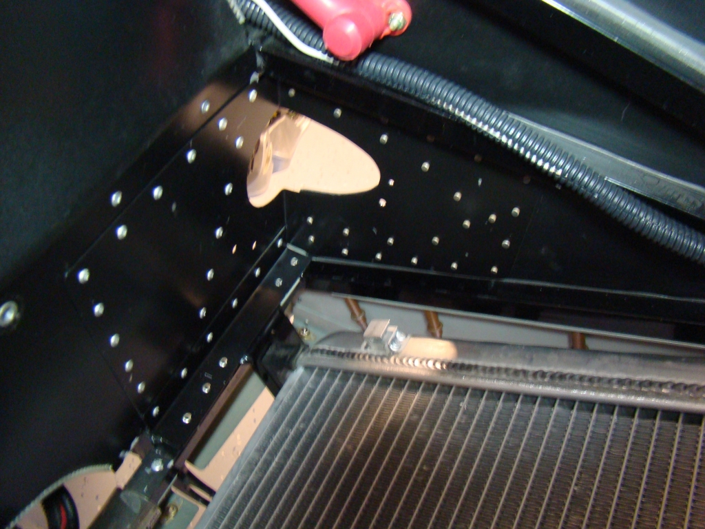
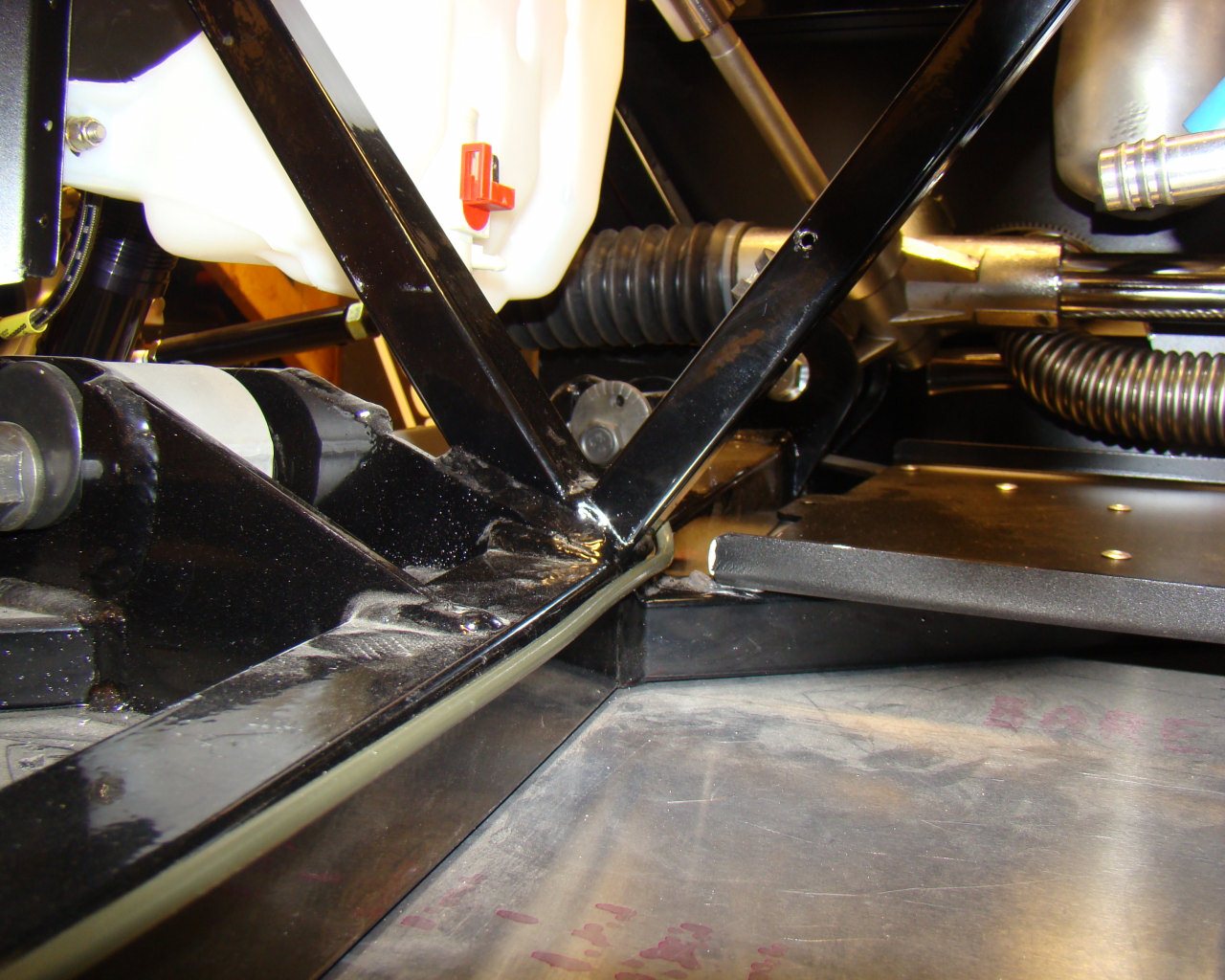
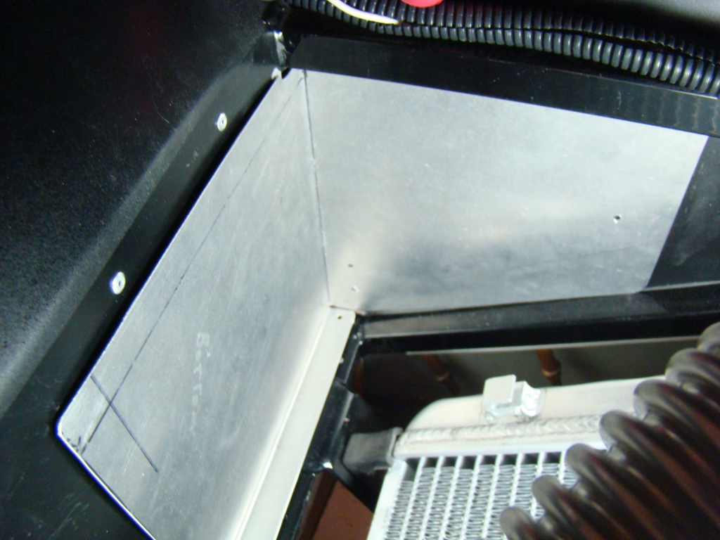
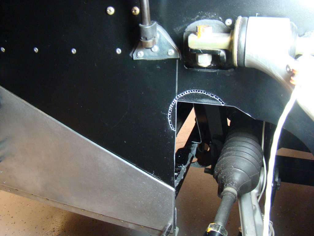
This is the
doubler, L-angle, shims and lower radiator closeout panel riveted
as an assembly. The lower radiator closeout is the primed
area in the middle of the picture just aft of the radiator and
under the frame. The bottom of the panel attaches to the
undercarriage or belly panel which is part of the modified radiator
box. This seals and closes off the left and right corners which are
normally open on a stock GTM. For whatever reason, FFR's
design was a little flimsy and incomplete on the aft radiator box
corners.
Ultra Gray RTV
and self tapping 10-24 screws hold the opposing flange
on.
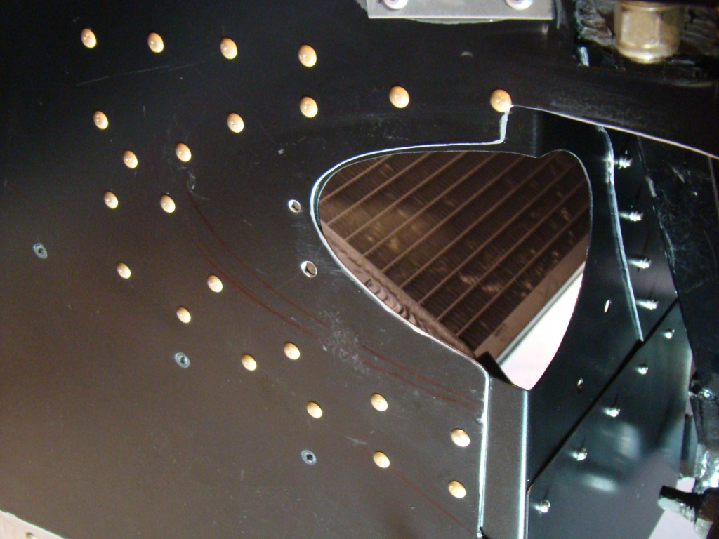
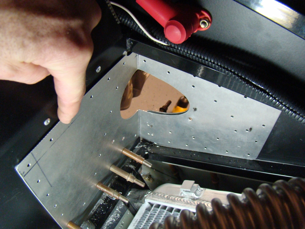
Note the cutout
to clear the frame member
Trial fitting and preparing the
attachment flanges off the car on the
doubler.
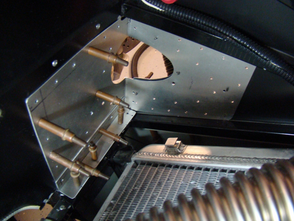
This is the inside
doubler that reinforces the corner and provides a little more
bearing surface to run the screws and bolts through for attaching
the duct later. It also ties in the lower closeout panel
which completes the closure of the bottom sheet metal panel under
and behind the radiator box aluminum.
After drilling through the assembly, I
used 3/16ths soft aluminum rivets. I actually bonded all the
pieces together and then did the
riveting.
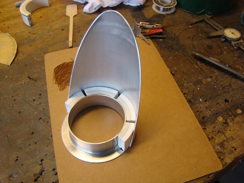
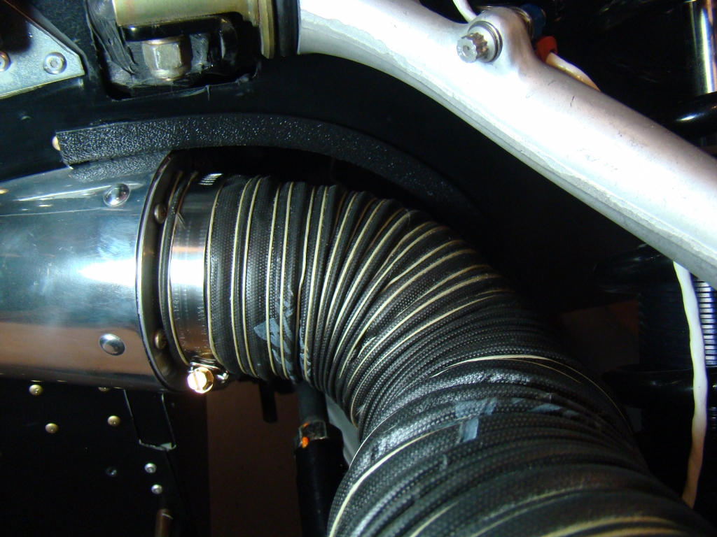
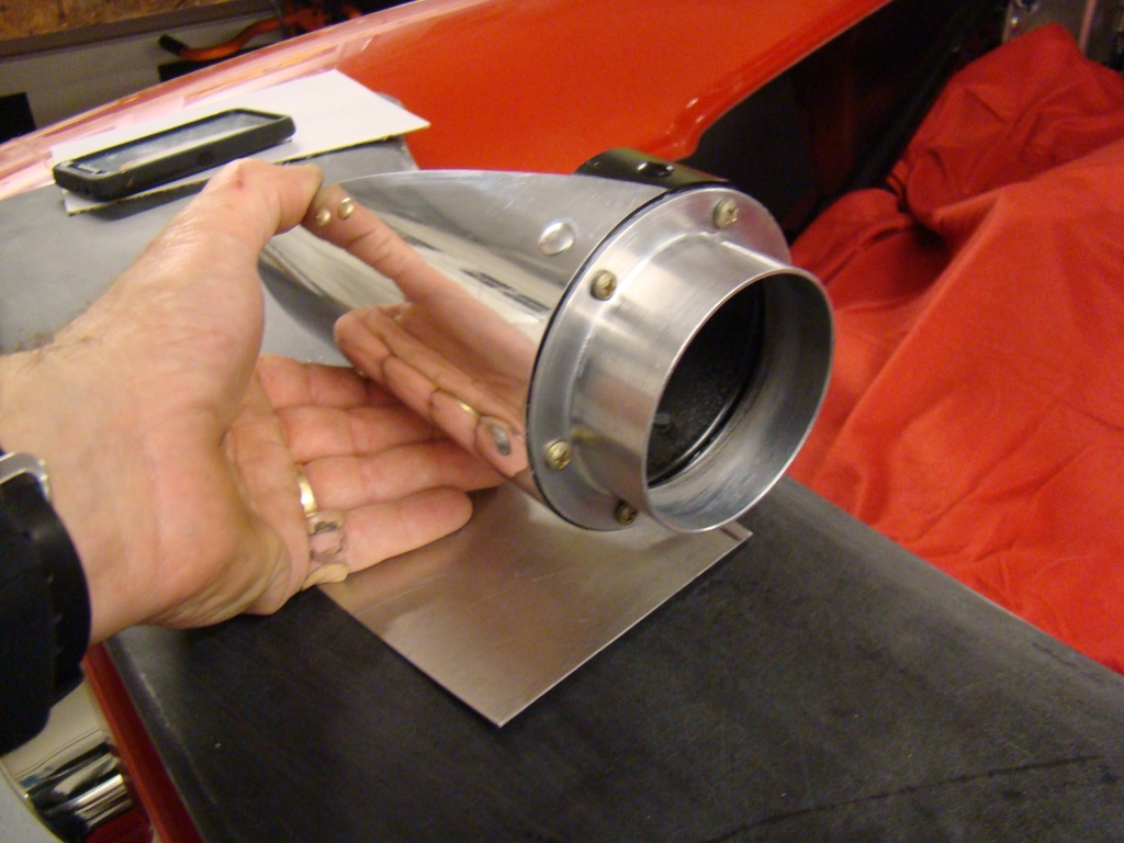
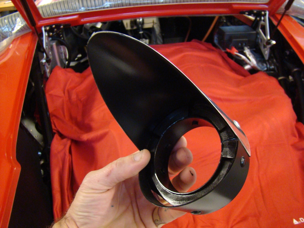
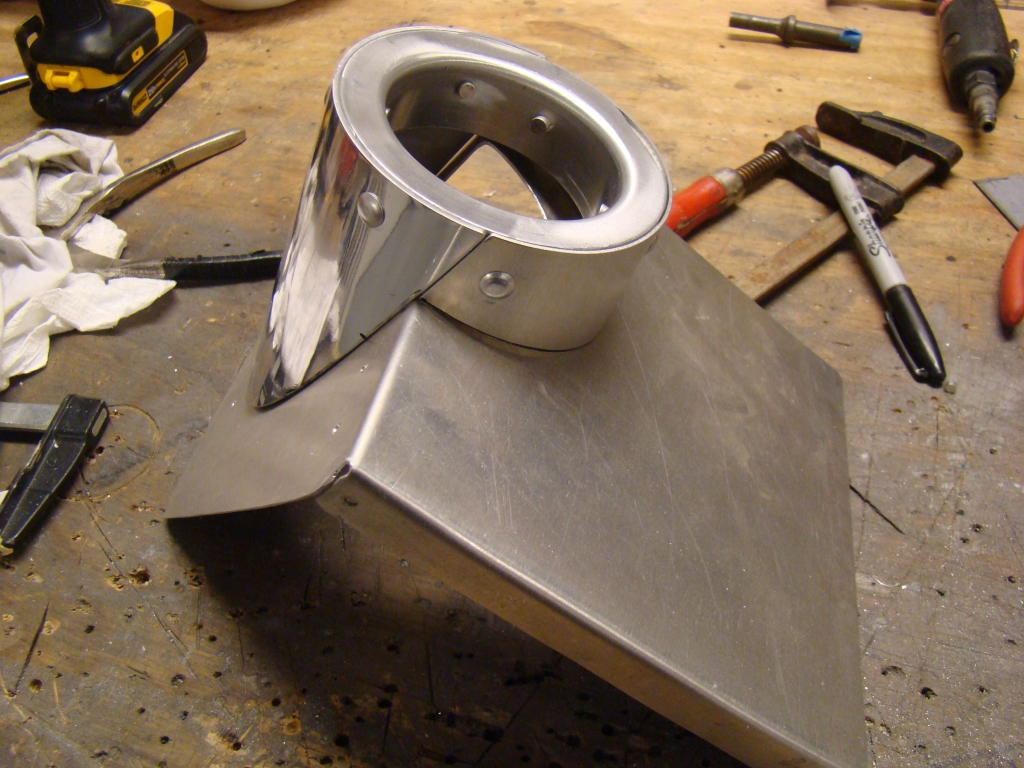
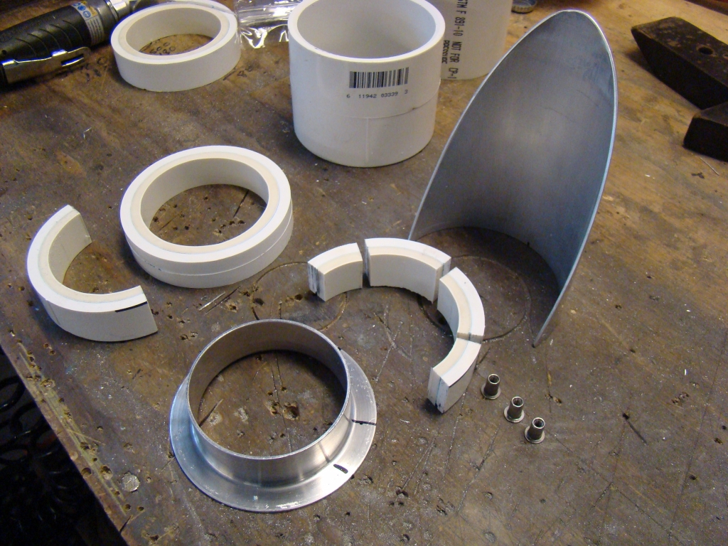
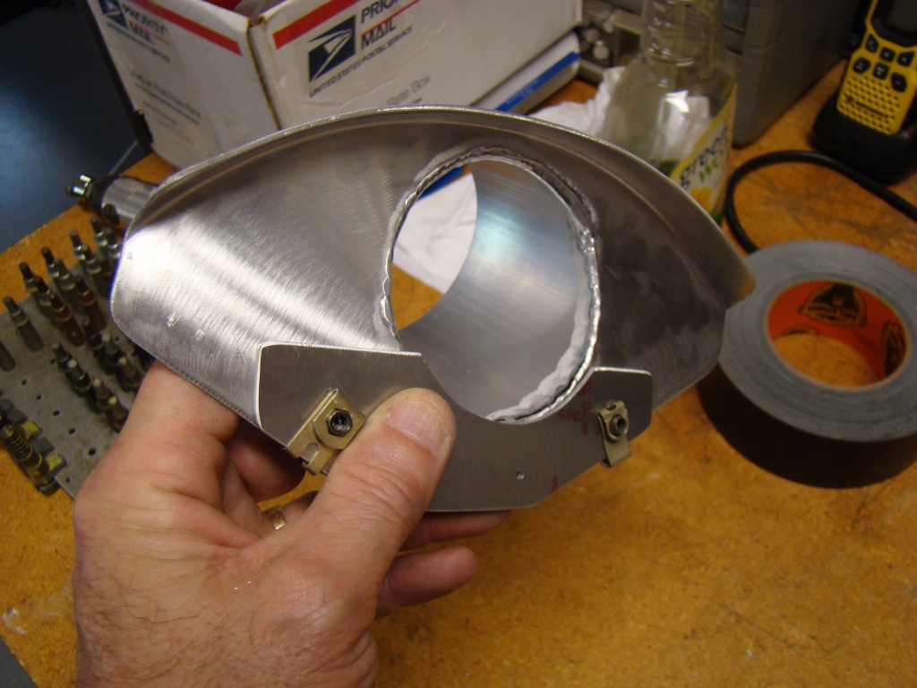
3"
PVC pipe and a coupler ended up making a perfect spacer that took
up the space between the duct diameter and that of the
flange.
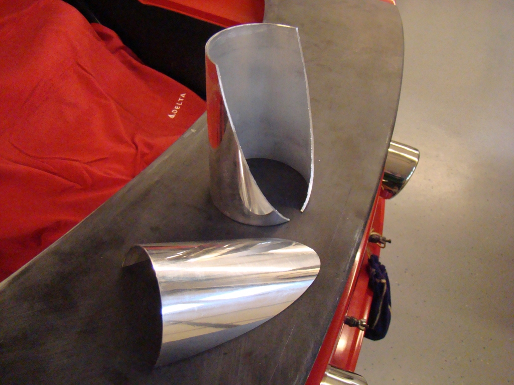

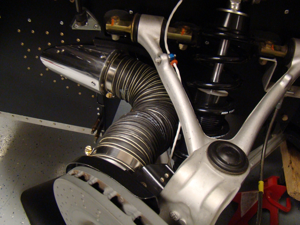
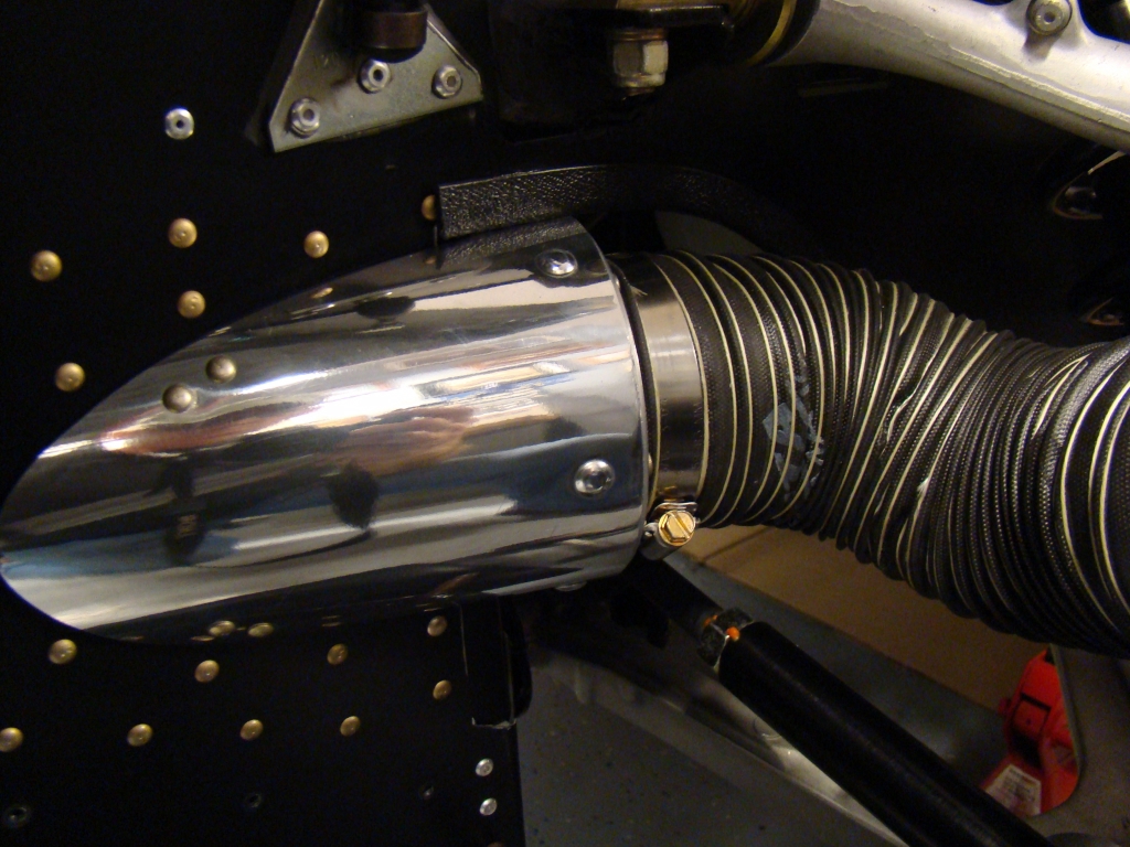
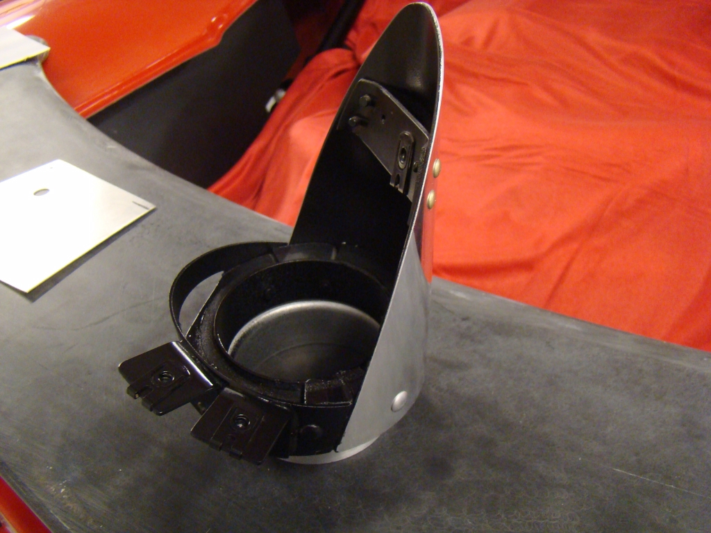
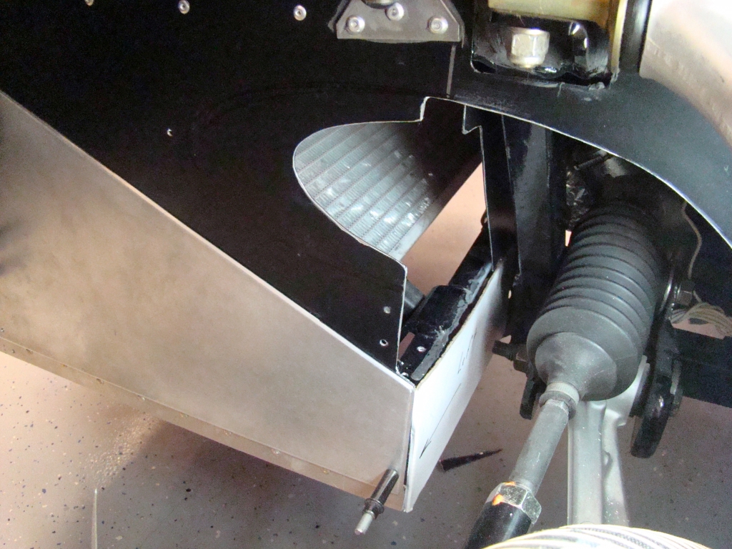
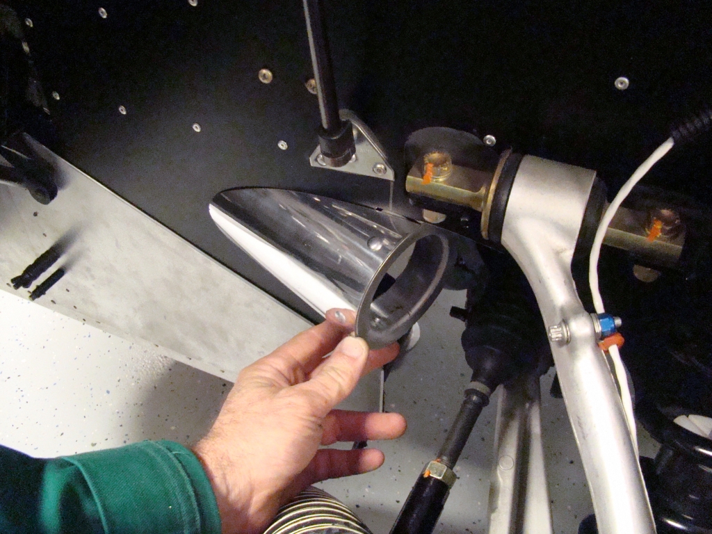
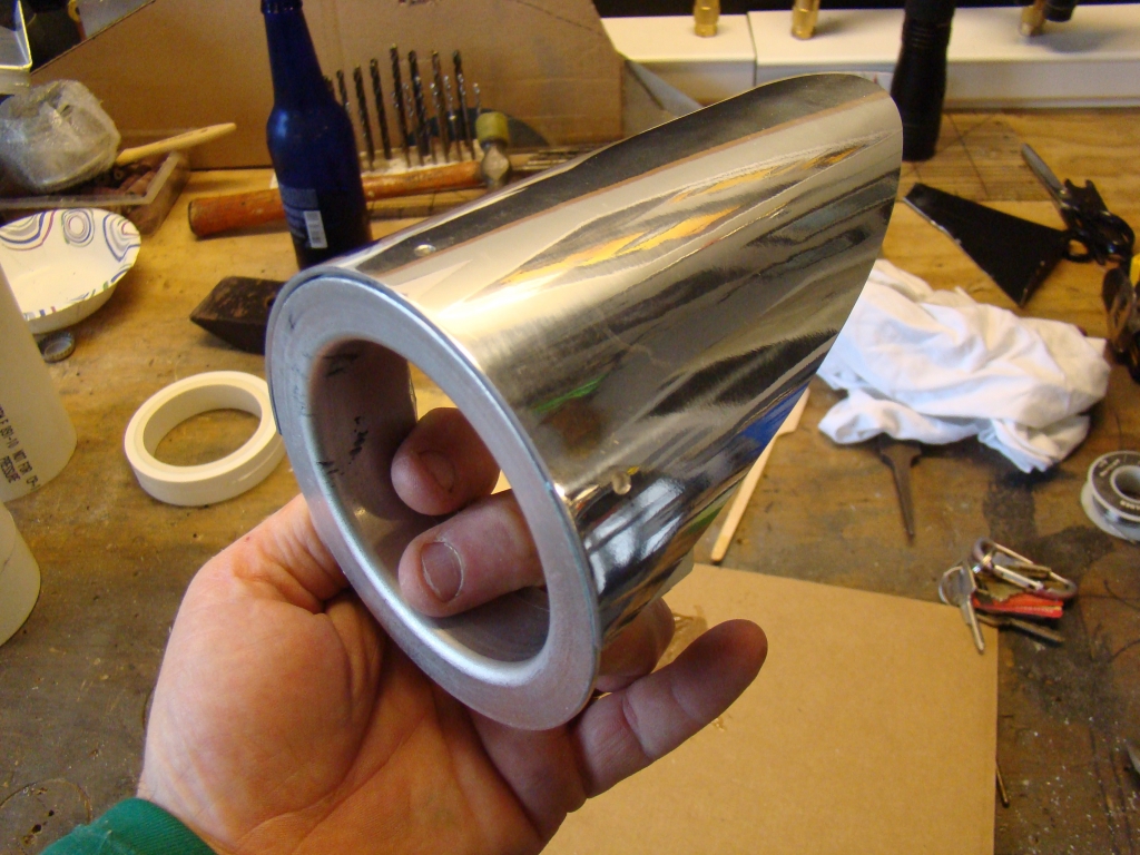
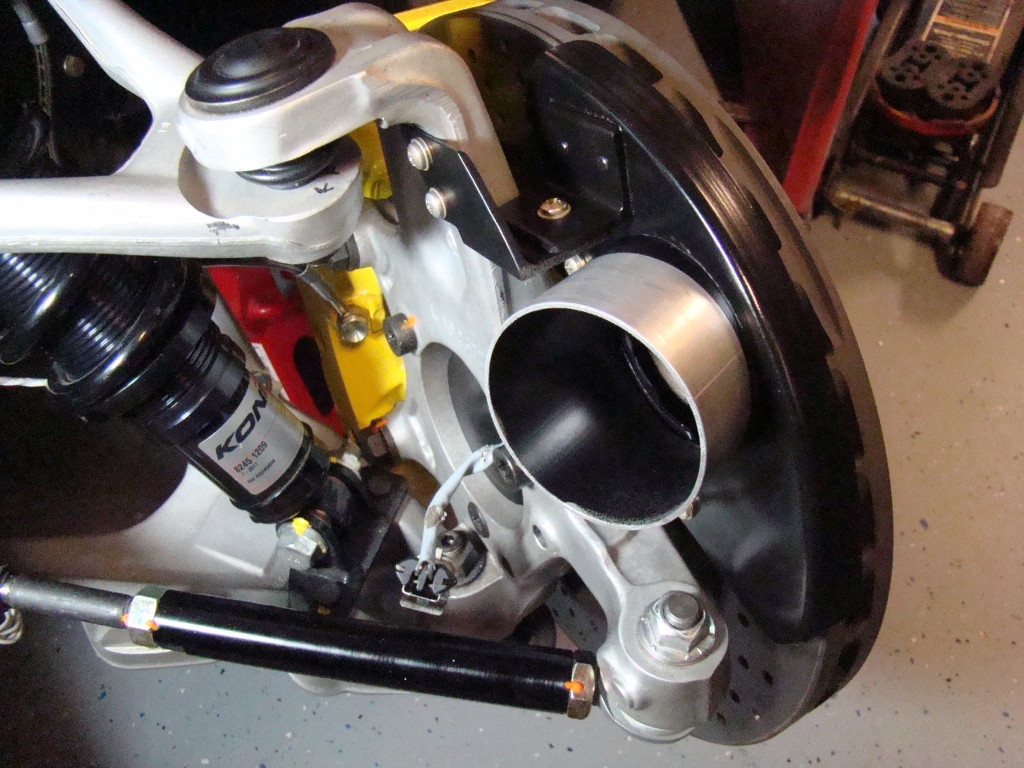
This was an
interesting challenge. I had to cut the duct at the right
point so that when at the correct height at the flange, the
remaining tapered body would lie flat against the side of the wheel
well sheet metal without need for a seal. I wanted a clean
look with all retention done from inside using clip style
nuts. The bandsaw I currently use doesn't accomodate a cut
like this without risk to the piece or the person cutting it.
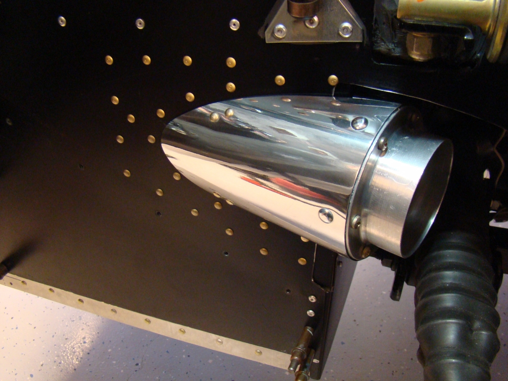
A good bandsaw would have worked with proper setup but this was
much easier. The two challenges are getting the cut lines correct
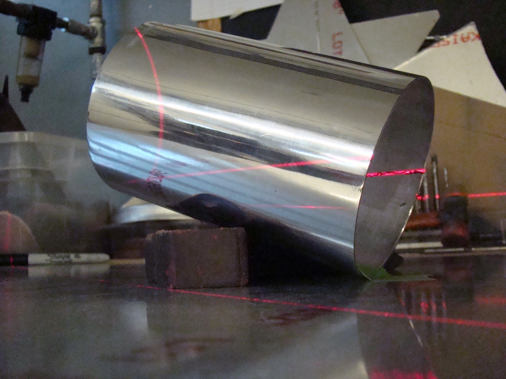
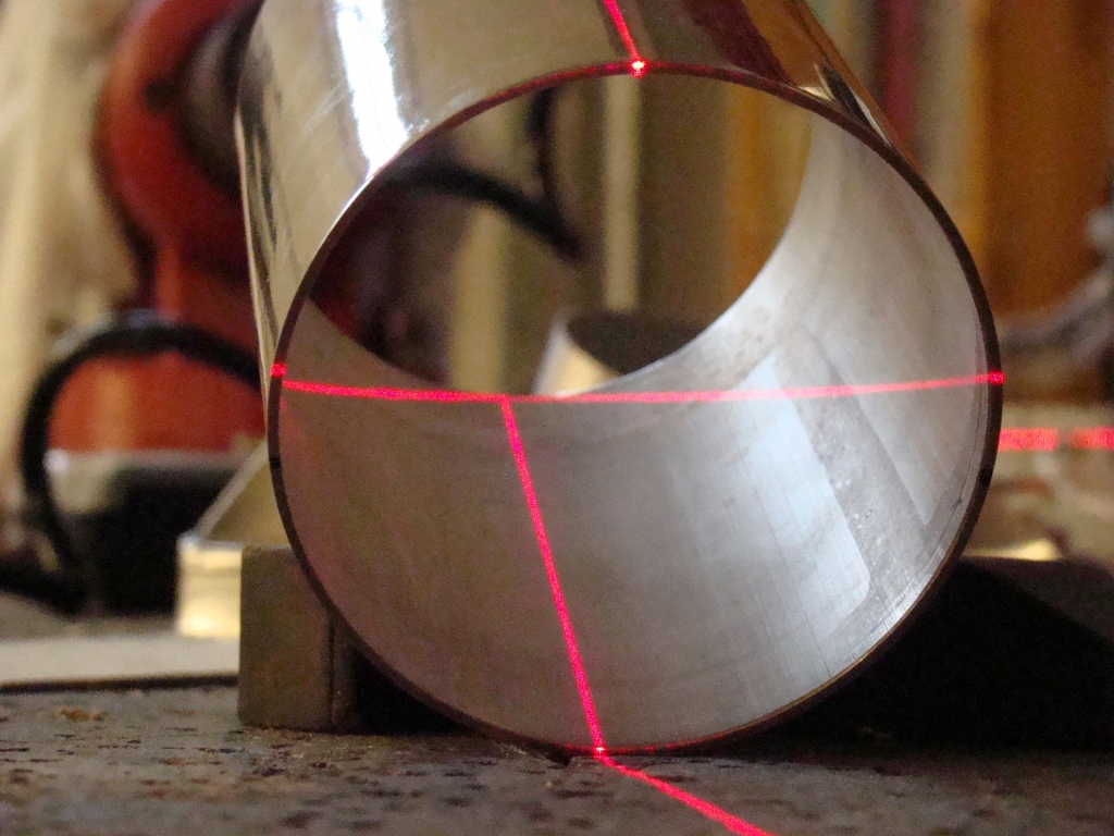
and then making the cut without error. I remembered I had a
double line self leveling lazer which worked perfect for projecting
the line for the cut. After I traced the lines, I made the
cut with a 3" cutting wheel.
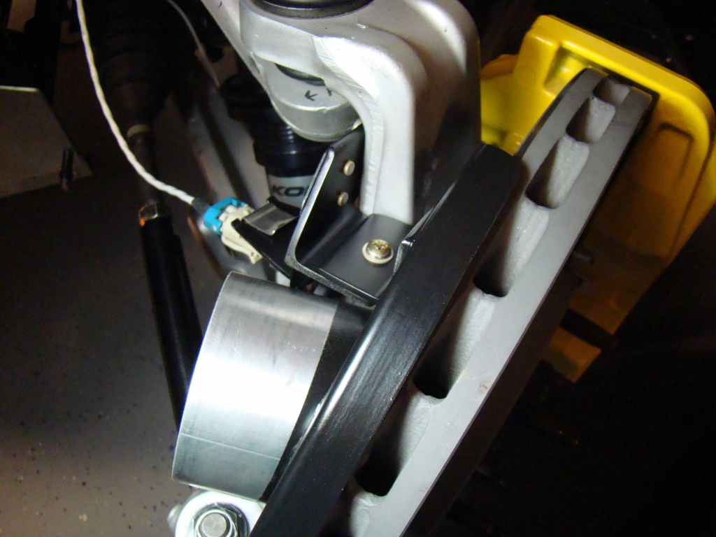

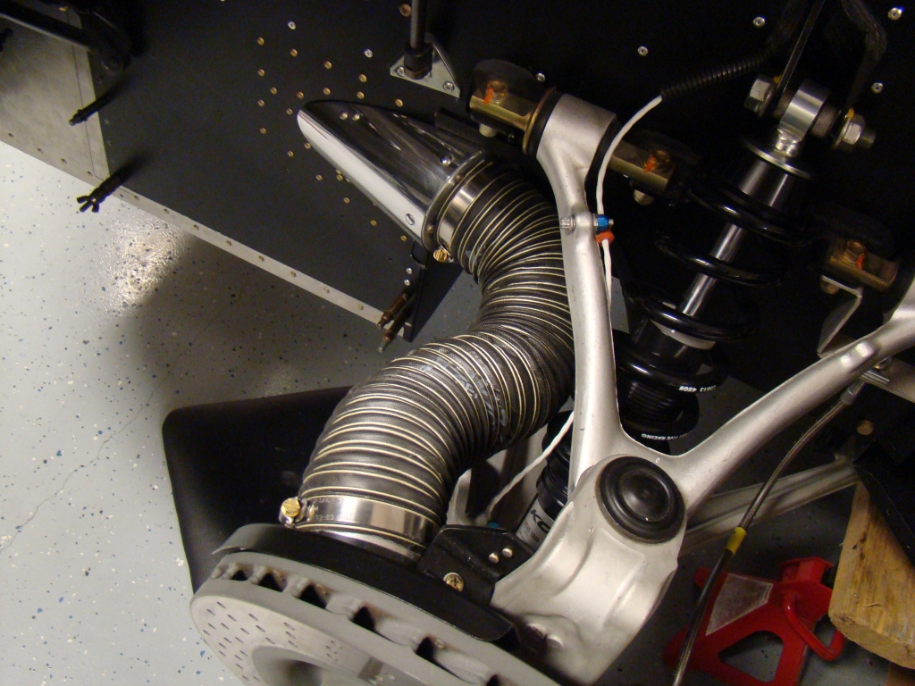
The modified
connector holder riveted to a new bracket.

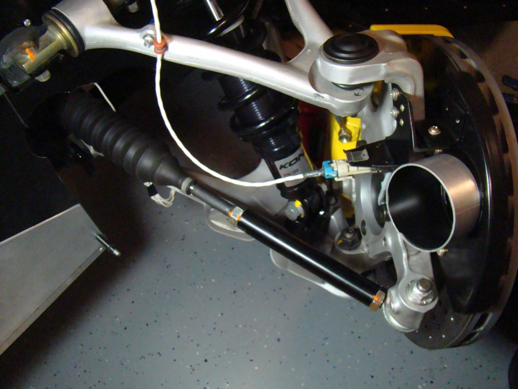
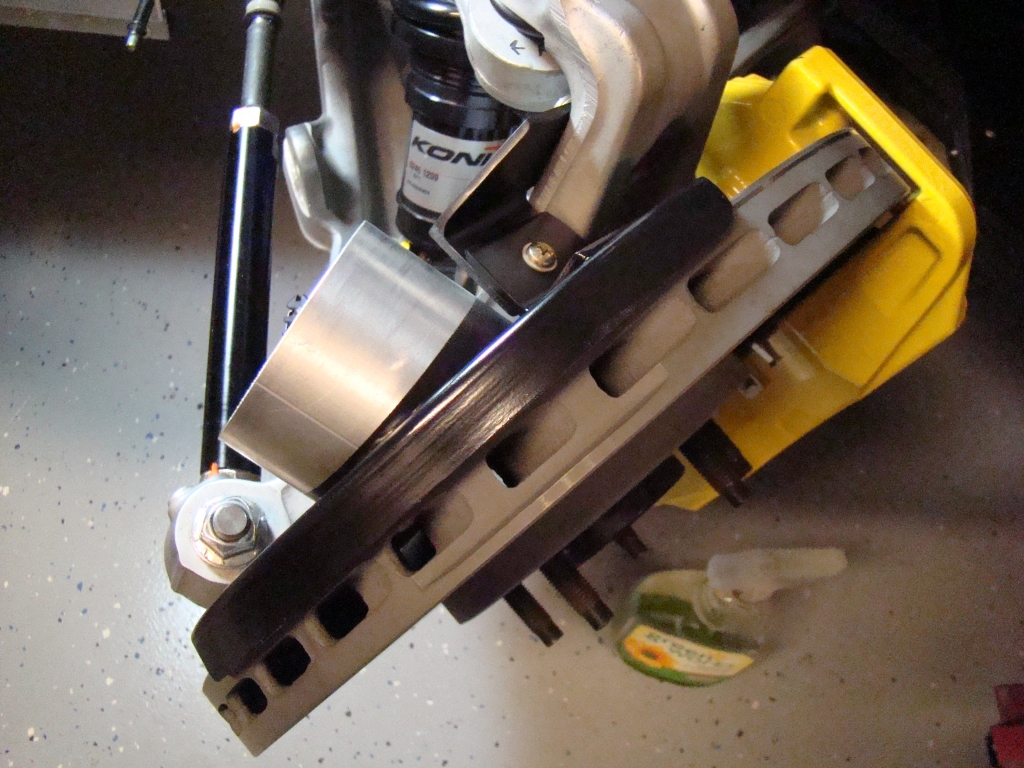
With spindle duct
mounted
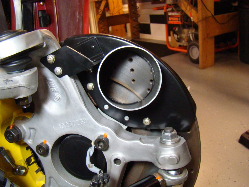
In
addition to the backing plate, I fabricated a .125 angle and tapped
the spindle for 10-24 screws installed with blue
Loctite.
I cut off the wheel speed sensor connector mount
at the bend, leaving enough steel to attach a backing plate for the
spindle duct. I saved the piece I cut off to be riveted to an
aluminum bracket and re-used for the speed sensor connector
later.

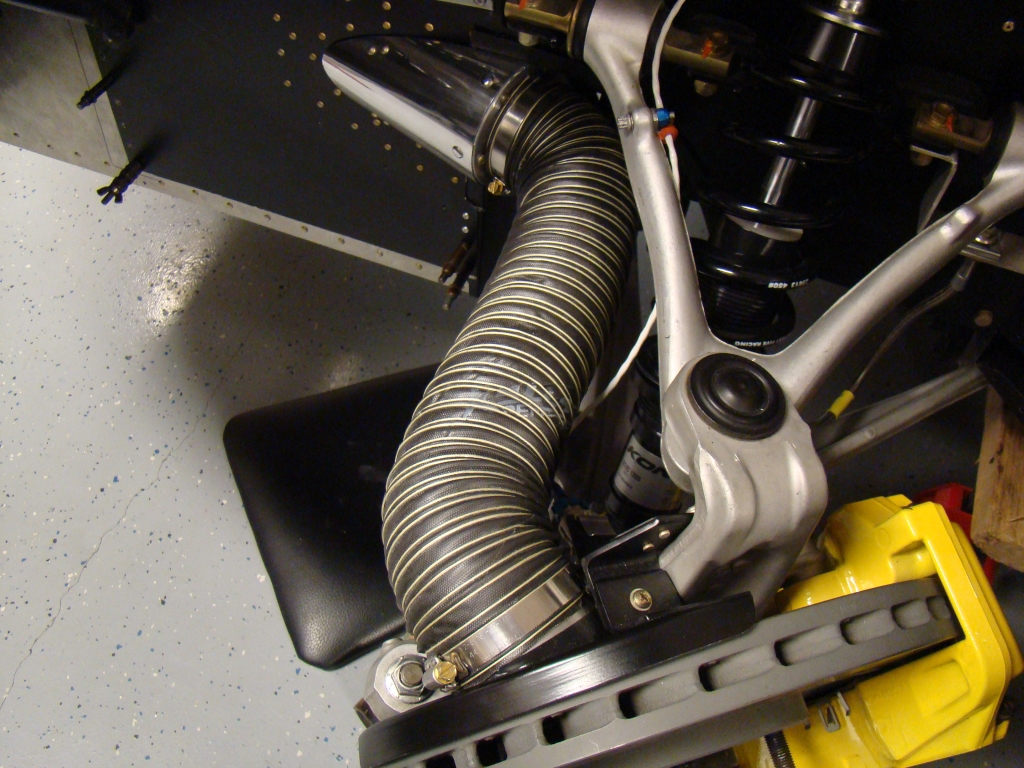
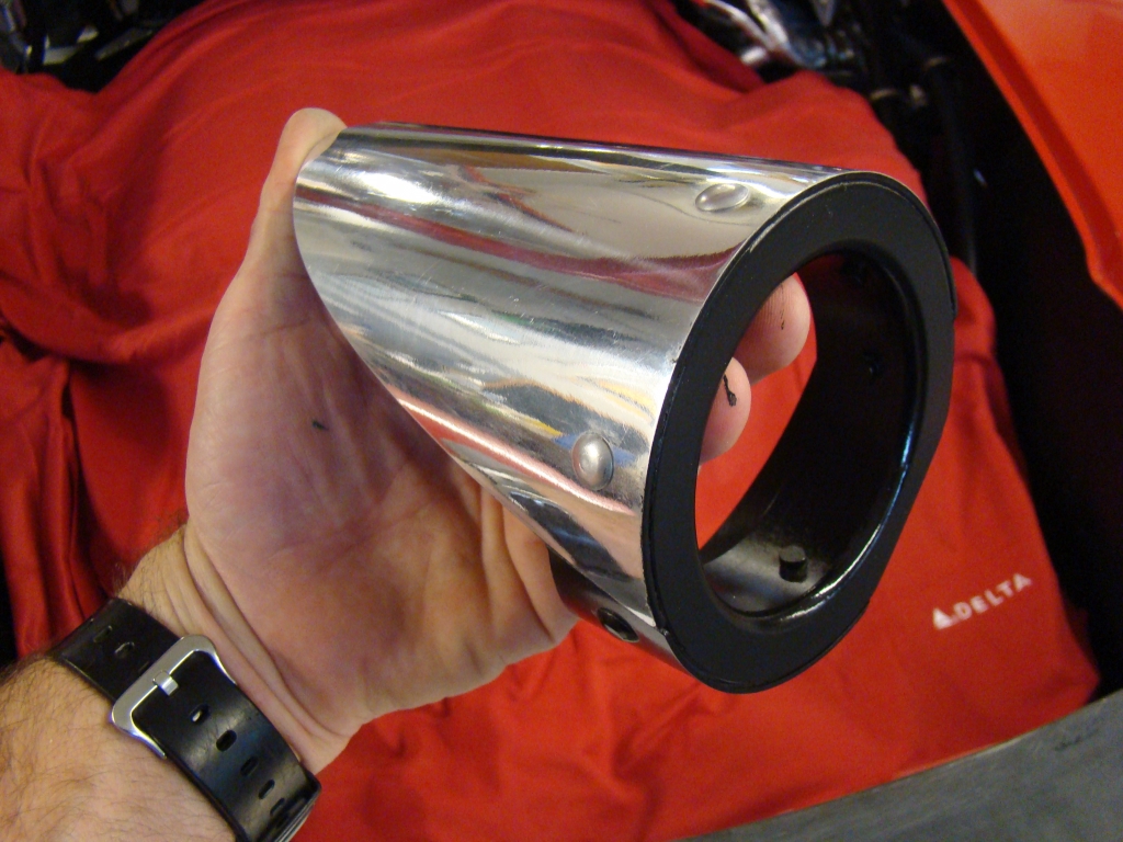
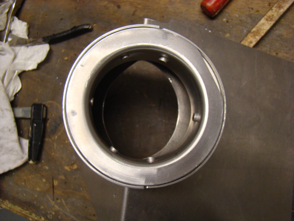
The parts below are AllStar performance spindle
mount ducts. The flanges are 3" flanges from Aircraft
Spruce.

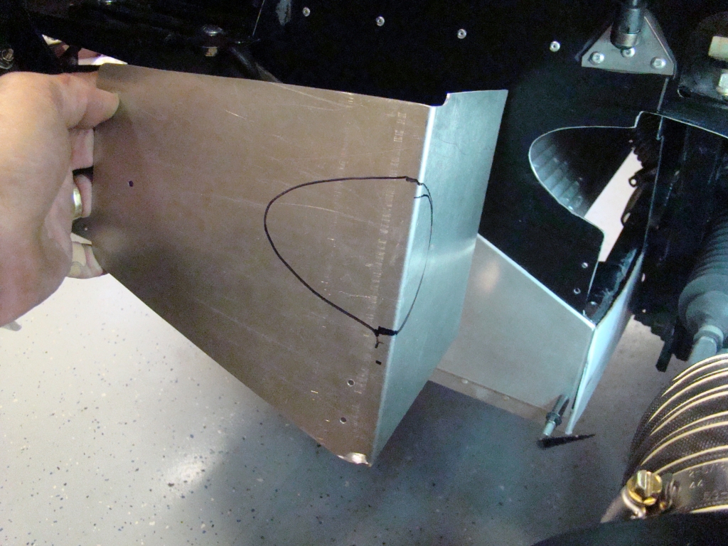
After looking over the radiator box and airflow,
not to mention access and all the other considerations (Angle,
interference, airflow temperature, velocity etc), I had to figure
out the solution and then build to it vs hacking things up.
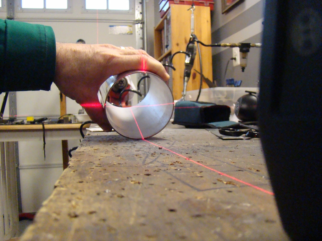
By the time I made the cut, I already chose a four inch Spetre
polished tube as the best way to get the air flowing at an
angle. I also had to figure out how the flanges and duct
would attach before knowing all of this would fit and not interfere
with the steering at different heighs of the suspension. I
used a jack and moved the steering full left and right while
holding the 3" ducting in the approximate position to understand
how the duct would move and flex. Surprizingly, the duct
flexed like an accordian when angled properly. Anyway, I
began making the cutout a little at a
time.