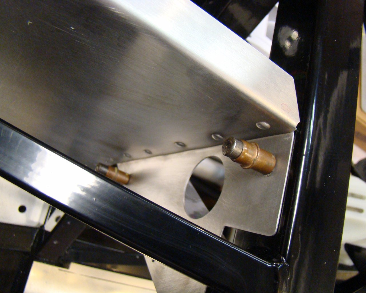
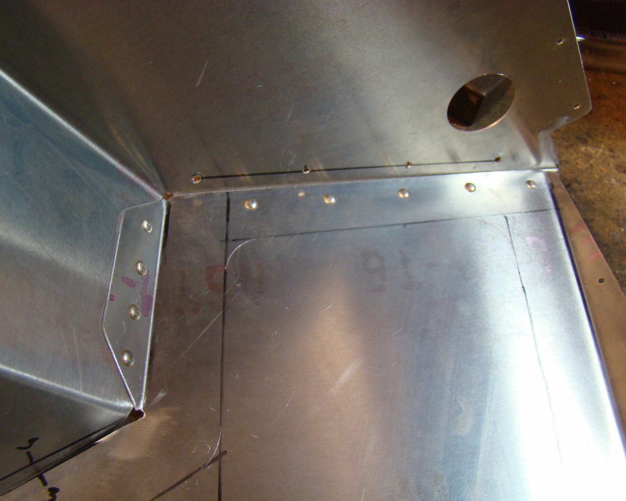
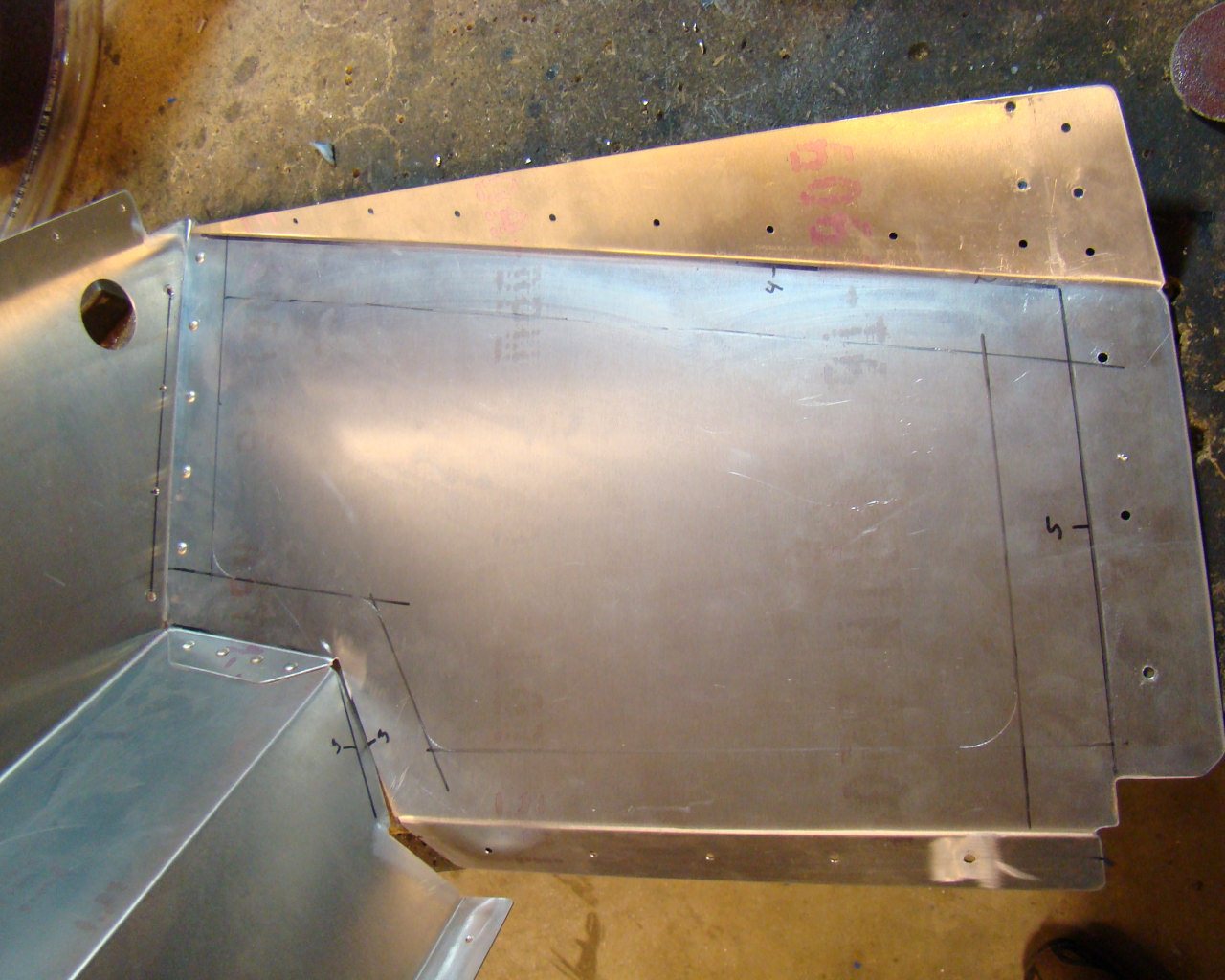
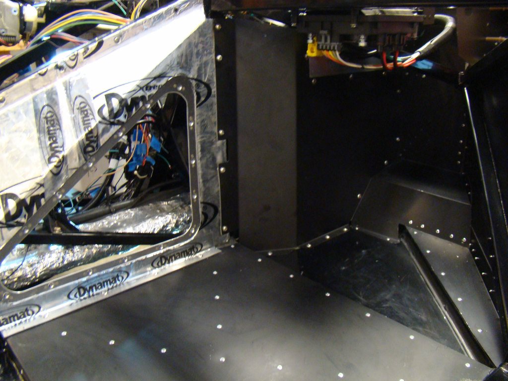
Working the Aluminum around the foot box is a bit of a challenge. The instructions don't exactly guide you through some important parts of the project. This is one of the most important areas of the build to consider maintenance down the road. Don't be in a hurry to rivet these until absolutely necessary. Consider all the things you are covering up. This is why it's a good idea to trial fit as much as possible and go through the manual several times to see where things will be and what may be difficult to access after the panels are in place.
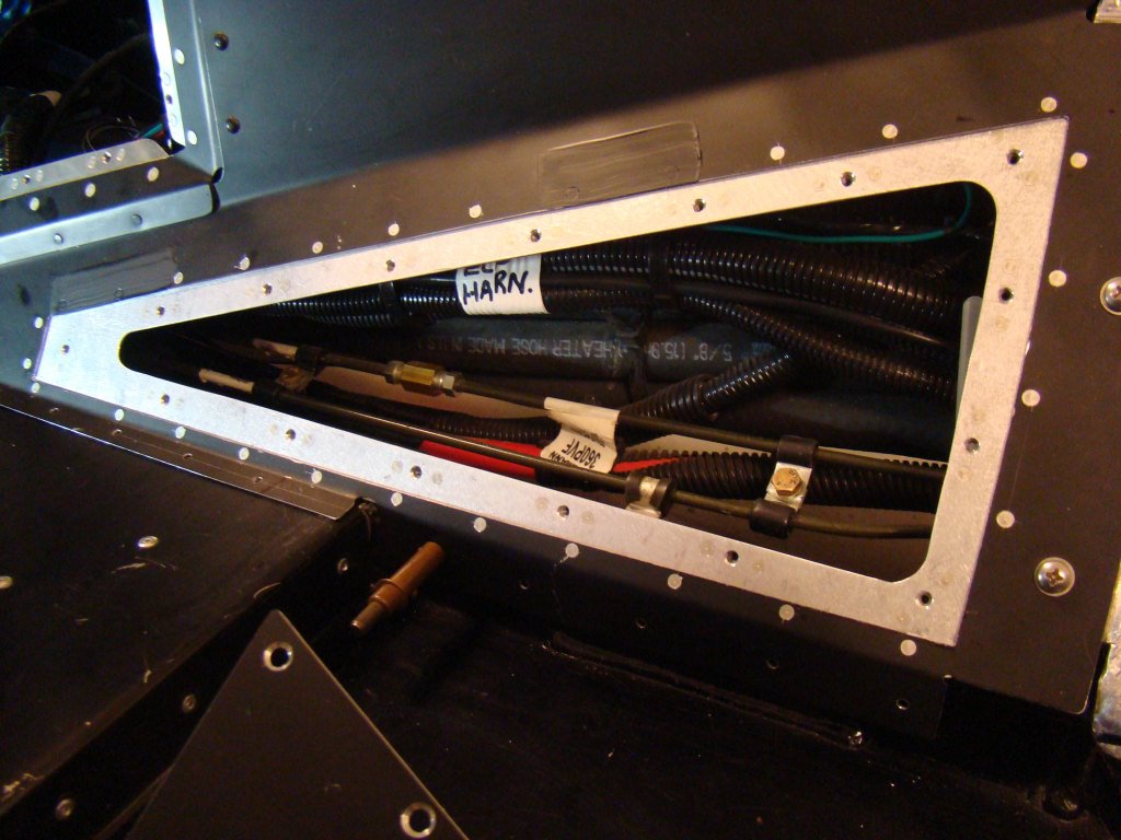
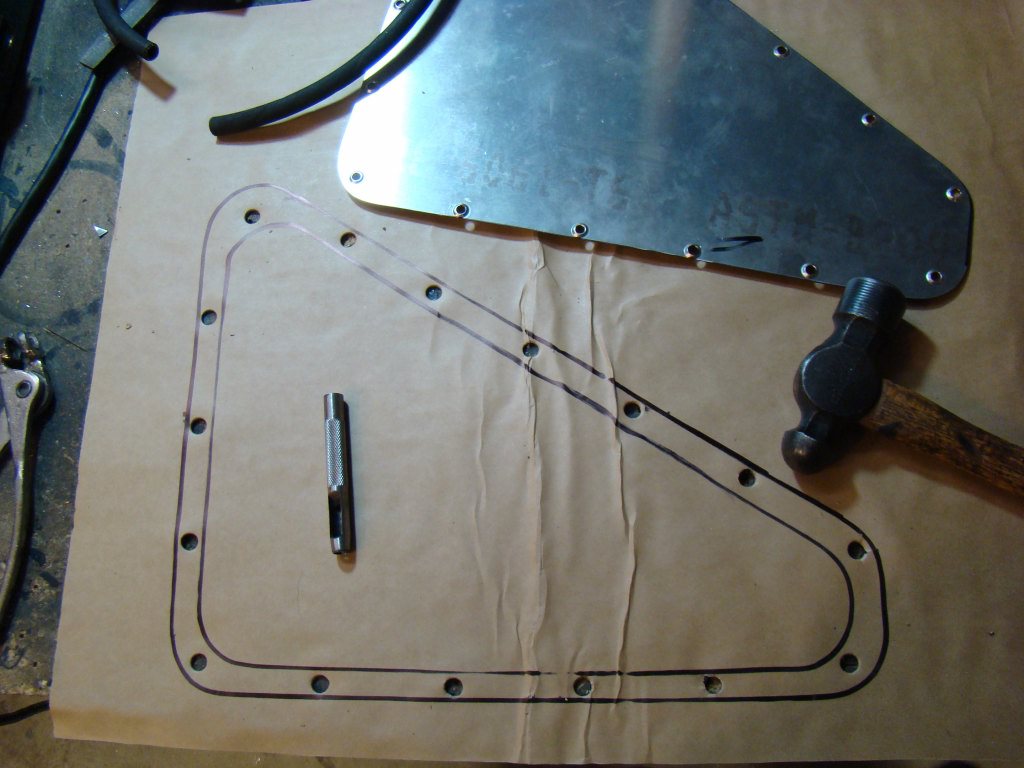
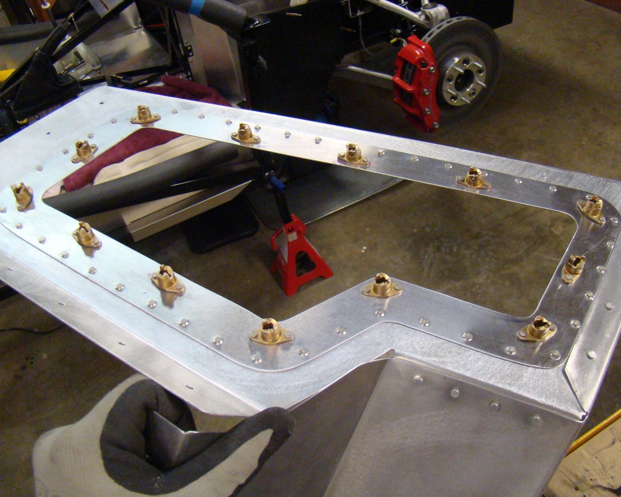
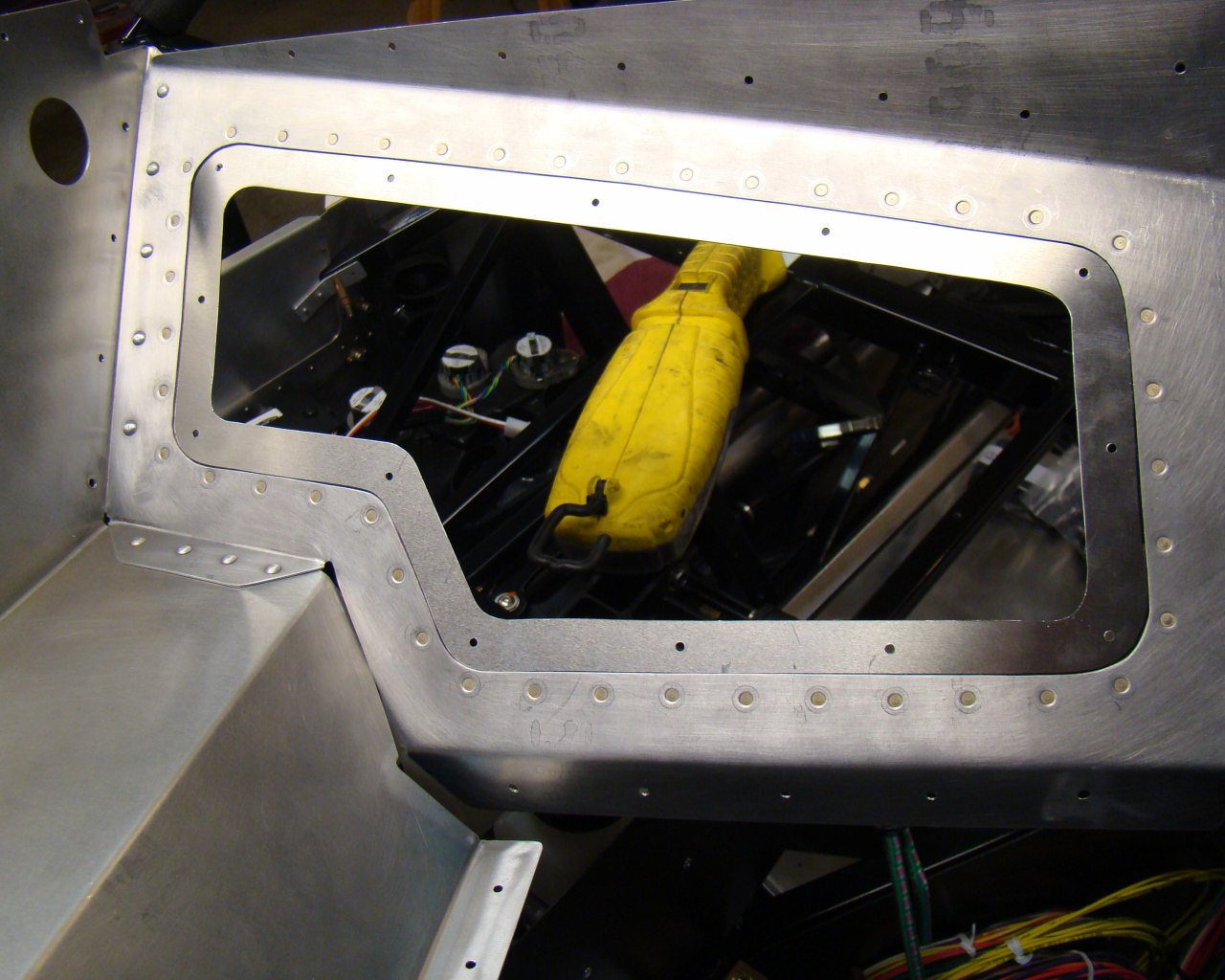
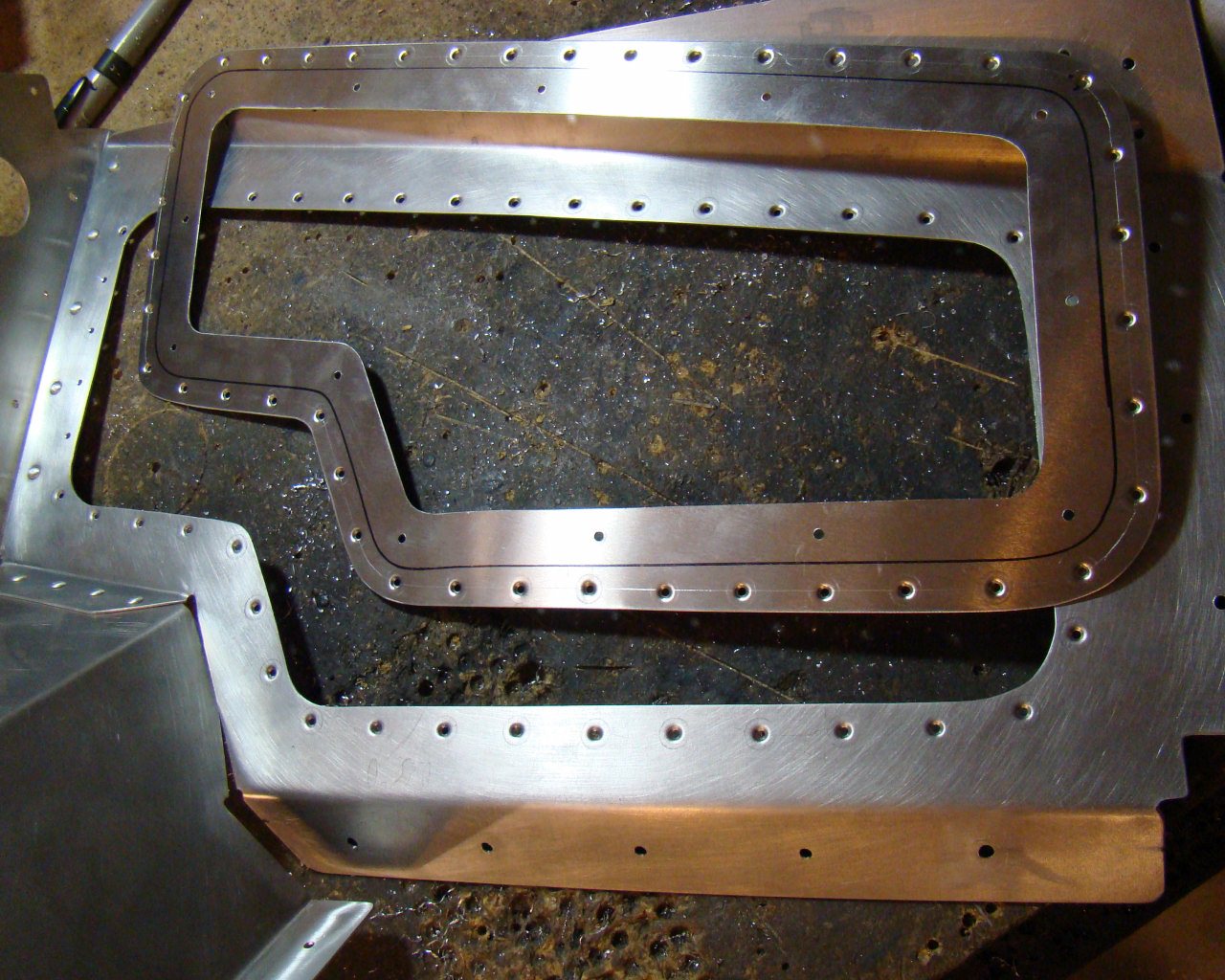
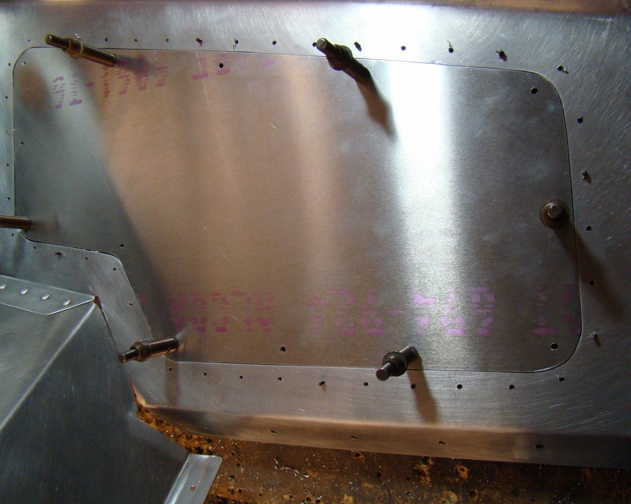
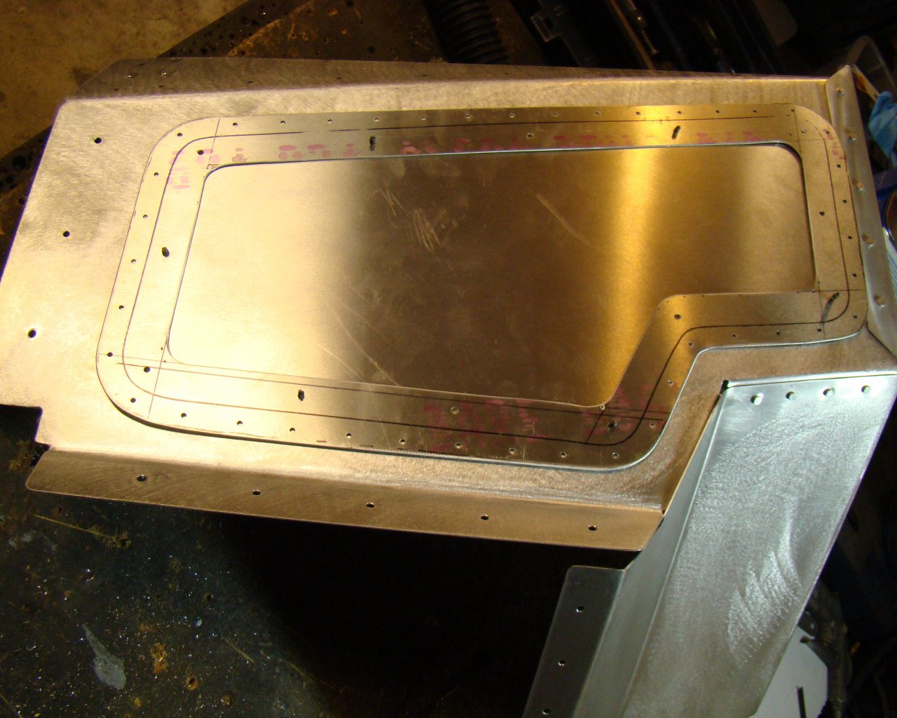
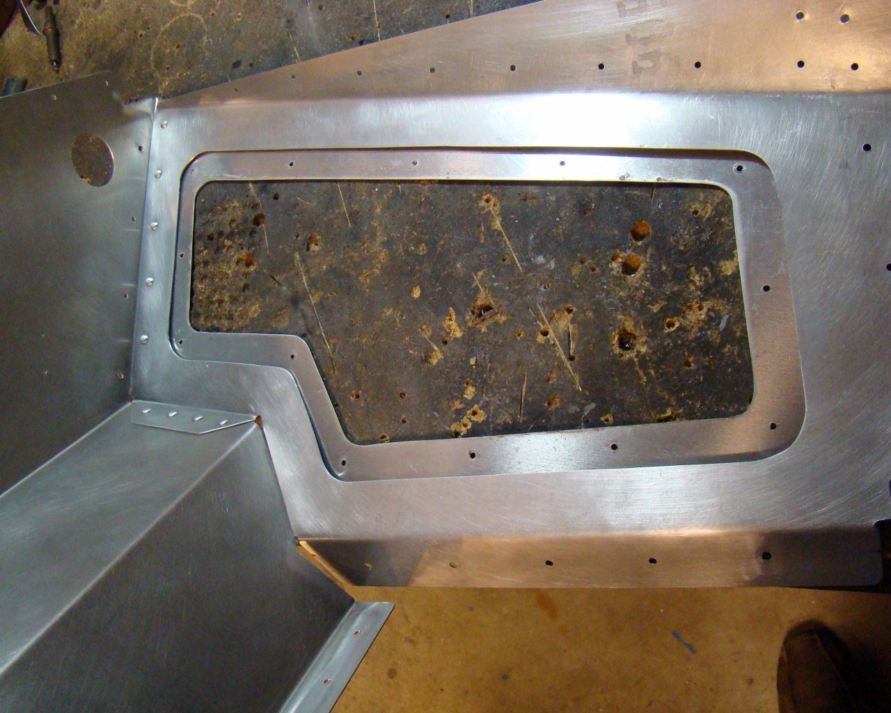
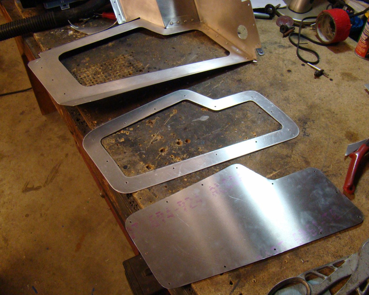
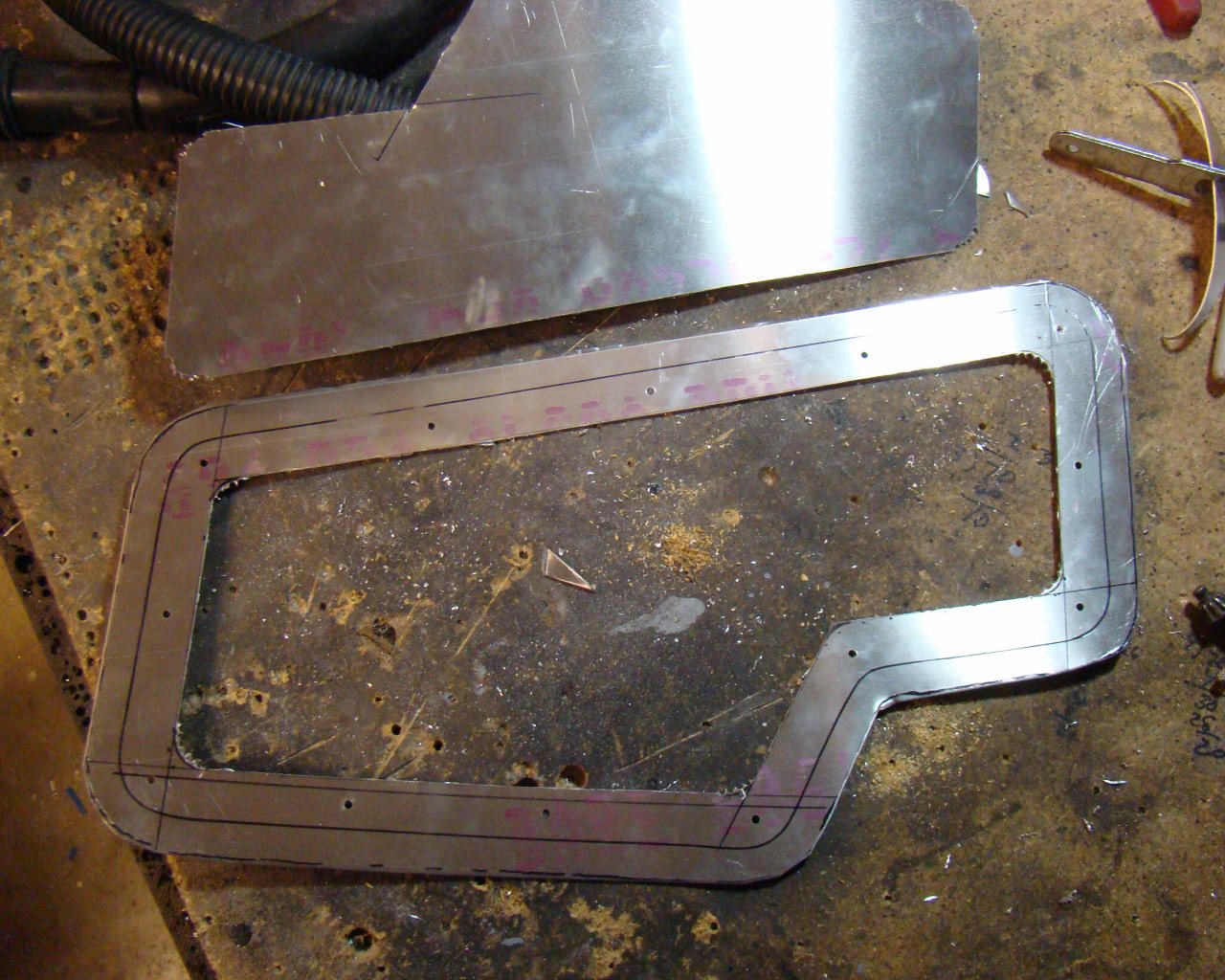
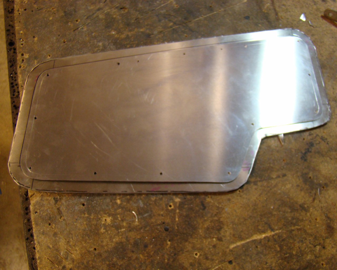
For the area around the center tunnel , I've decided to take the time to cut out access covers. I've ordered some extra aluminum to use for covers which I will fabricate. To do this, I will fabricate doublers and flush rivet them to the backside of the opening and then install aircraft nutplates to the flanges that extend approximately .5 inches inboard of the opening you see in the photos. A panel that duplicates the opening will be fabricated and drilled with holes for screws that extend through it into the doubler, creating a flush fit. Where possible I am using MS20470AD-4-X solid rivets
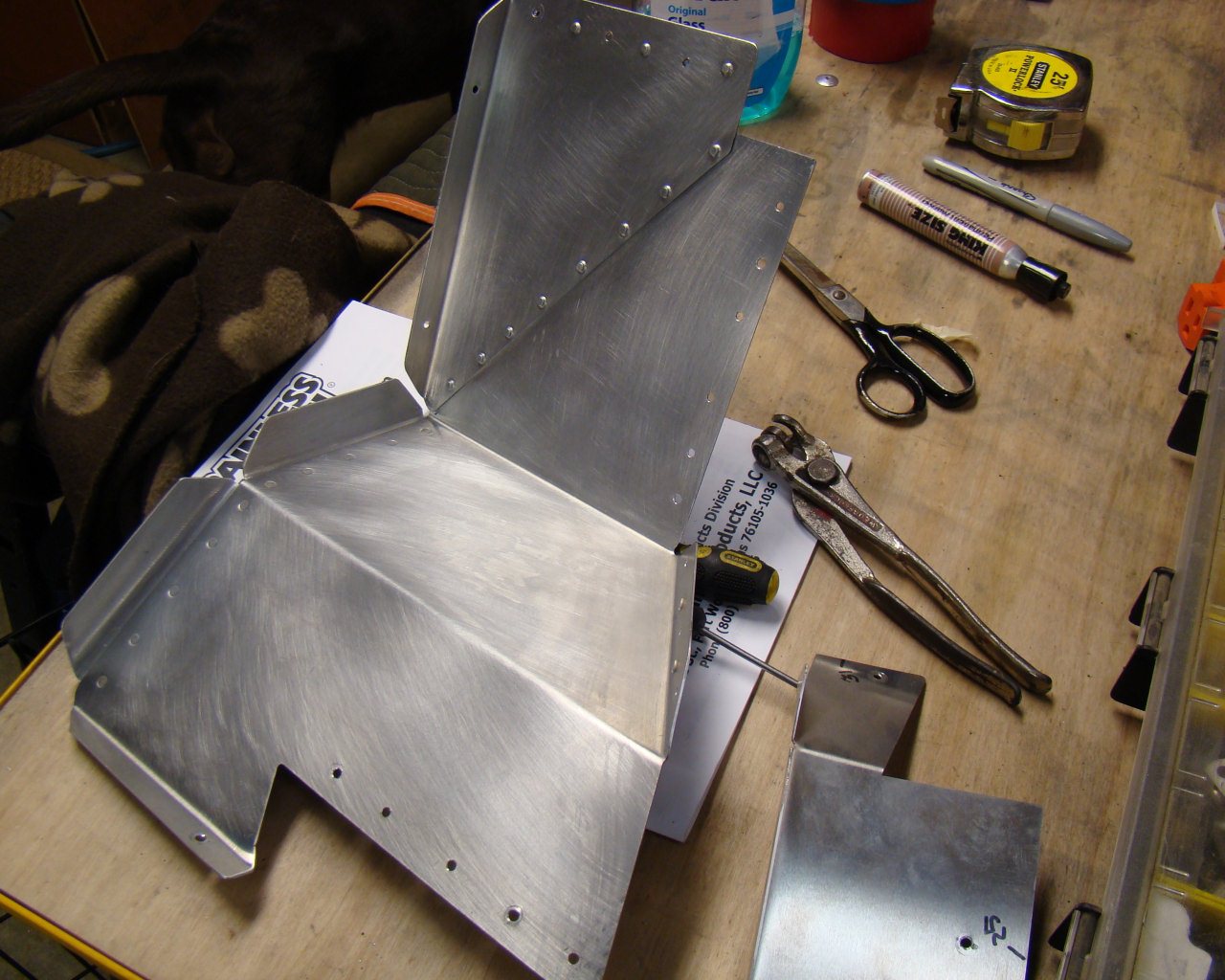
Not all panels can or should be solid riveted. Only those that can be installed as assemblies should be solid riveted. In other words, if you can rivet a few pieces together and still slide them into place do it. This way you can do it on the bench and then install them by section vs panel by panel. If you think about it, this will help if removal is required later. Combine sections to the extent possible but keep in mind, solid rivets are more difficult to drill out than the Pop rivets so if you anticipate that a panel may need to be removed later, make sure you think about access for drilling out the rivets. For the assemblies already solid riveted, pop rivets can be used to finish up the job.
NOTE
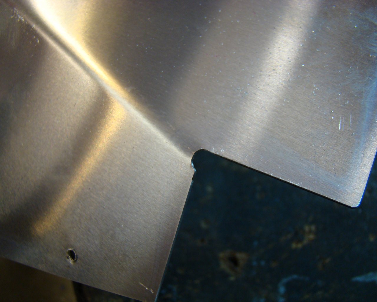
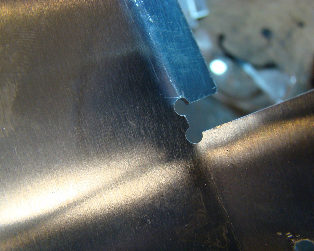
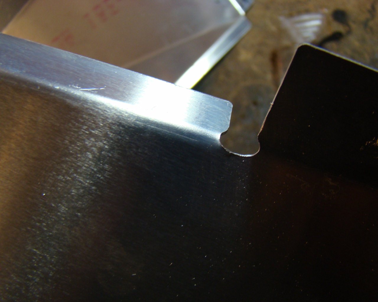
IMPORTANT: WHEN YOU GET TO THIS AREA, FACTORY FIVE HAS YOU TRACE THE PANEL AND FRAME OUTLINES ONTO THE ADJACENT PANELS. SOME PANELS OVERLAP IN STRANGE WAYS. ALTHOUGH MANY FIT NICELY AND THE FACTORY FIVE INSTALLATION PREVENTS MANY FLANGES FROM BEING EXPOSED, THE OVERLAPS ARE SOMETIMES PROBLEMATIC. SOME HAVE PRELOAD AND LACK CLEARANCE. IN CASES WHERE PRELOAD PREVENTS PROPER SEATING OF PANELS DUE TO RADIUS INTERFERENCE, RELIEVE THE CONTACT AREA MY REMOVING SMALL AMOUNTS OF METAL WITH A FILE. IF IT'S OBVIOUS THAT METAL CANNOT BE REMOVED WITHOUT A LARGE CUTOUT, TRIAL FIT THE PIECES WITH THE FLANGE LOCATED ON THE OPPOSITE SIDE OF WHERE FACTORY FIVE HAD THEM.
FOR ALL PANELS THAT HAVE SHARP CORNERS AND RELIEF NOTCHES, DEBURR
THESE AREAS. THERE WILL NO DOUBT BE VIBRATION WITH THE
PERFORMANCE OF THESE CARS. VIBRATION WILL CAUSE CRACKS AND
WREAK HAVOC ON OTHER THINGS LIKE WIRING, COMPONENTS THAT ARE
TOUCHING ADJACENT FRAME MEMBERS OR OTHER PARTS AND MANY THINGS THAT
ARE NOT DISCUSSED IN THE MANUAL. TAKE THE TIME TO CORRECT
THESE AREAS AND MOUNT THEM WITH THIS IN MIND. DEBURR THE
CORNERS!
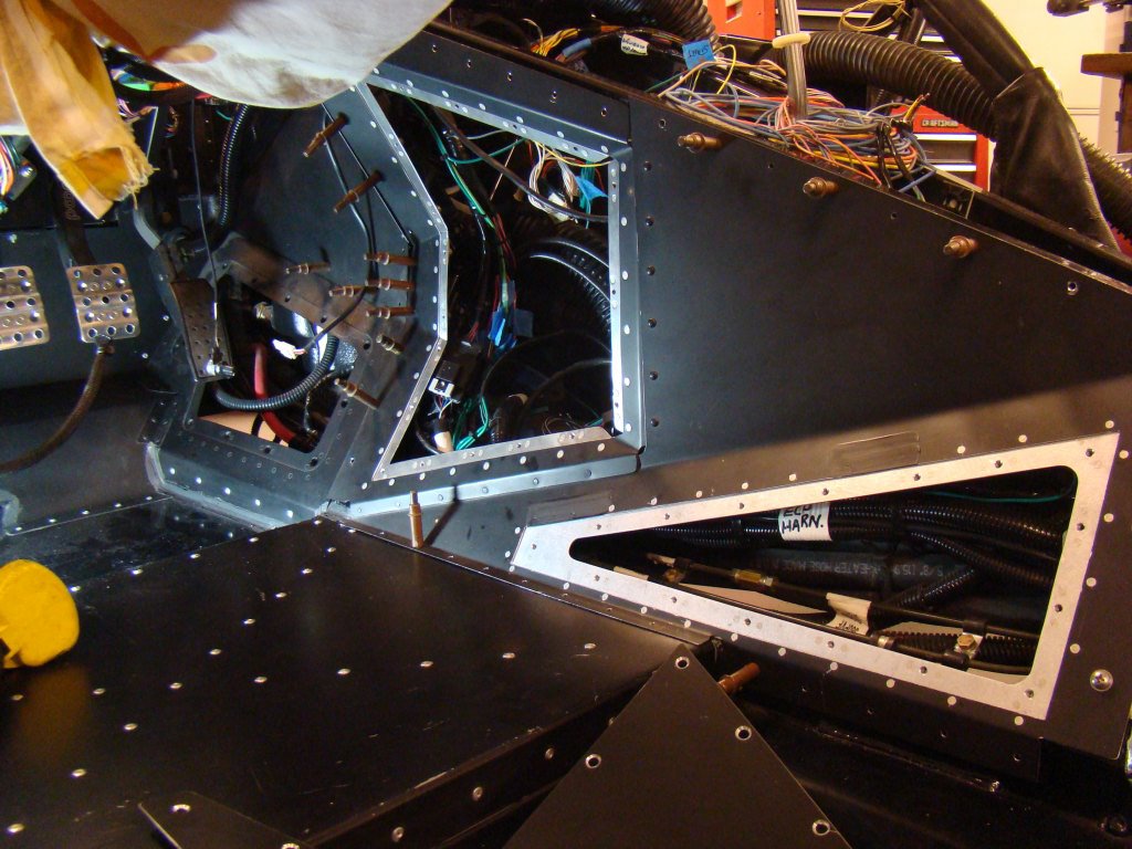
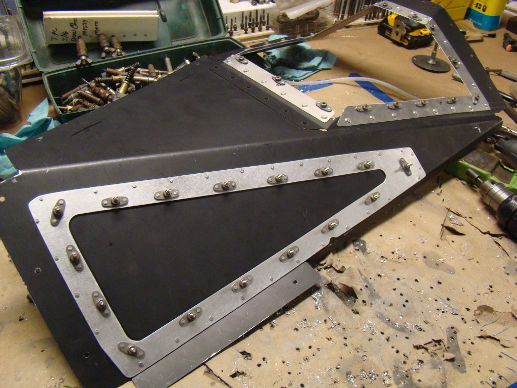

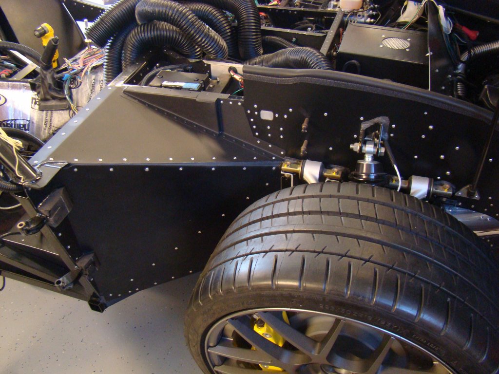
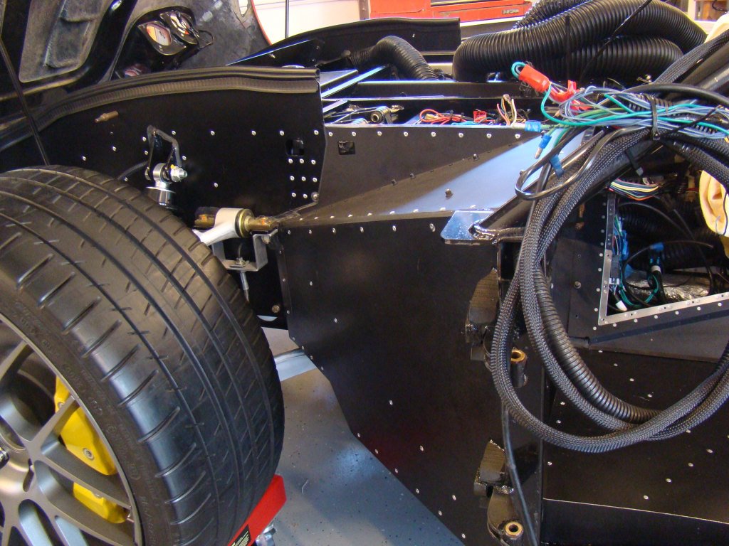
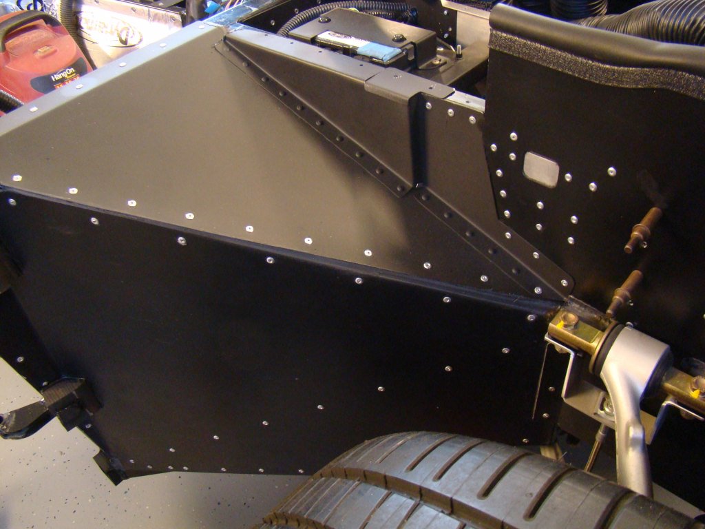
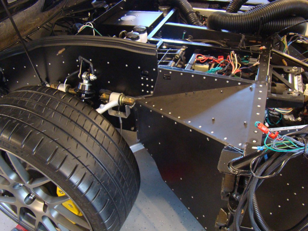
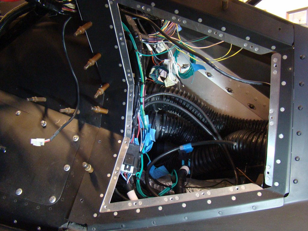
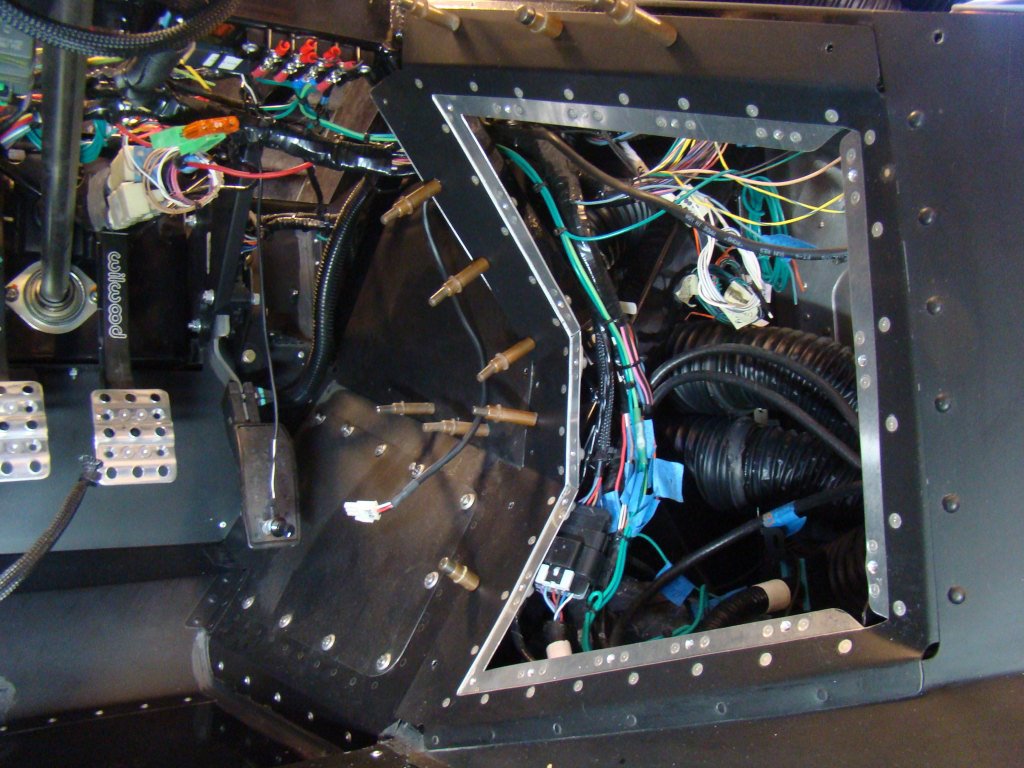
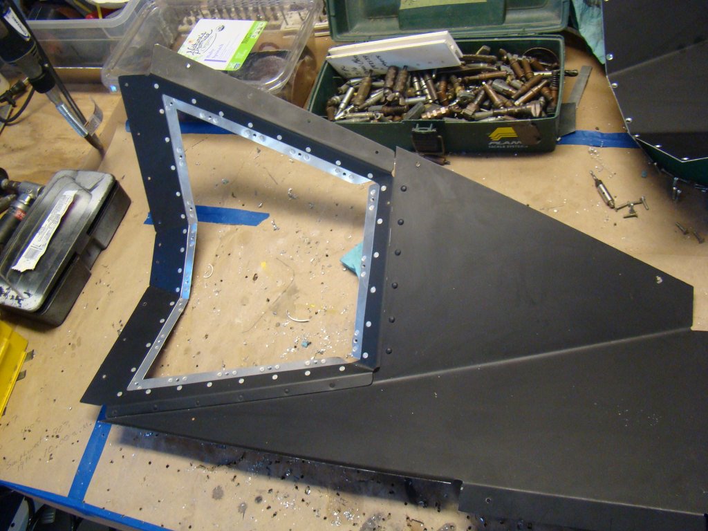
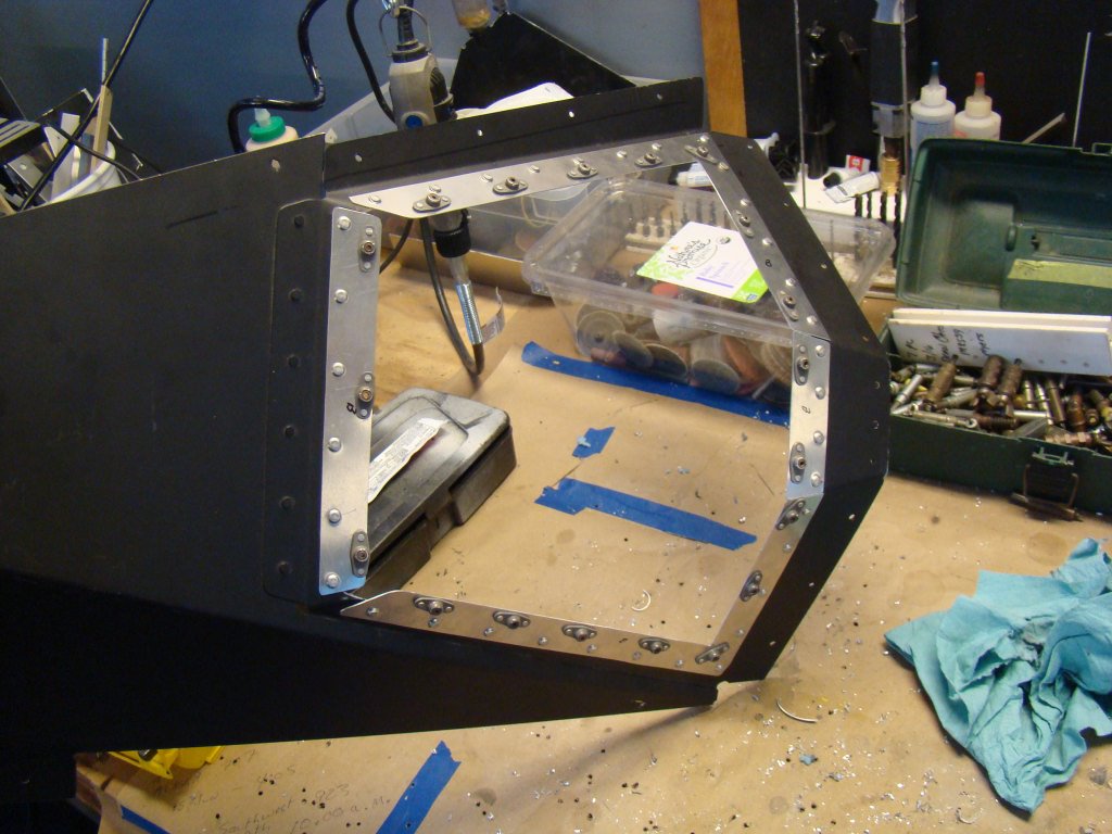
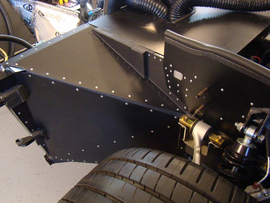

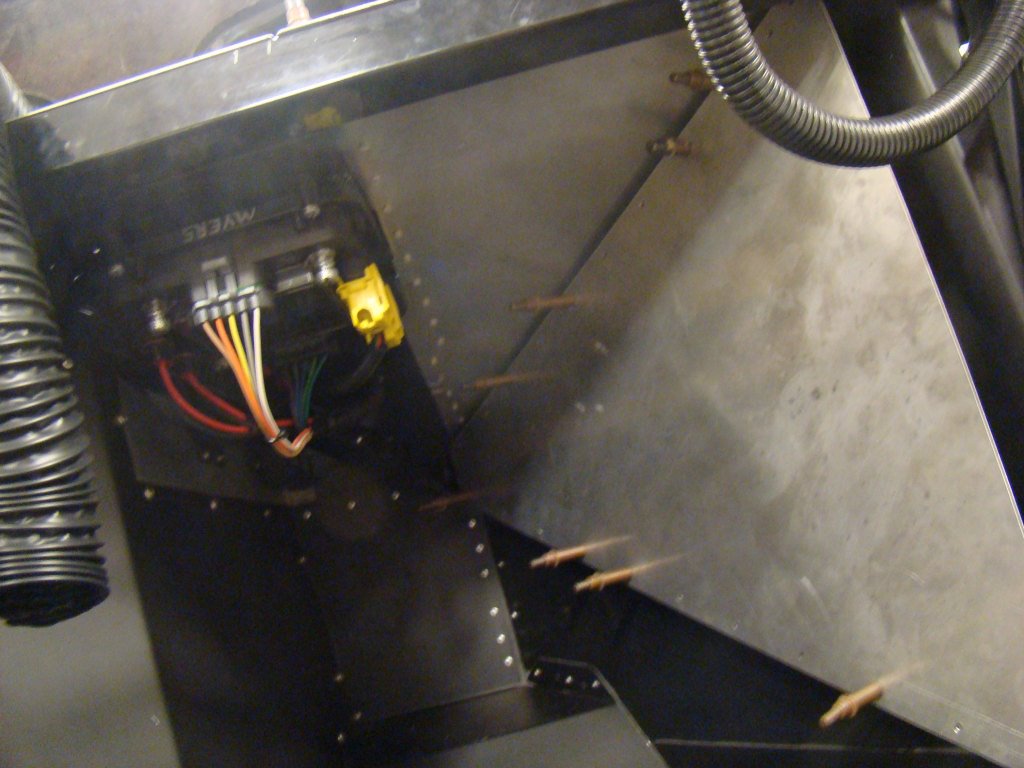
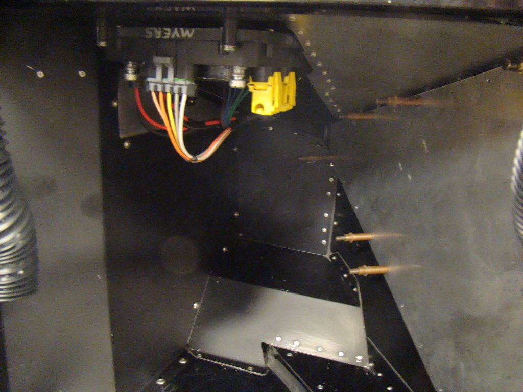
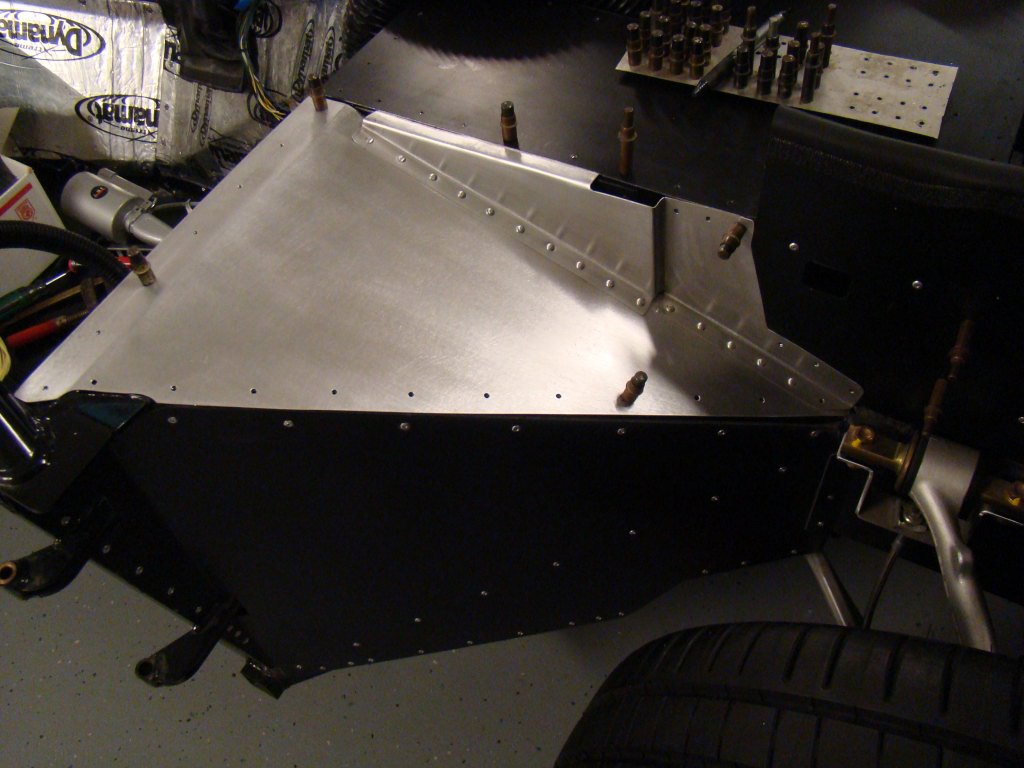
DRIVER AND PASSENGER FOOTBOX ALUMINUM
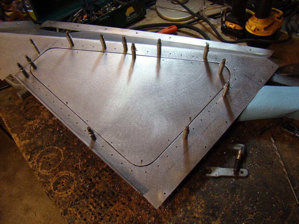
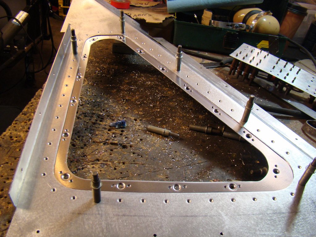
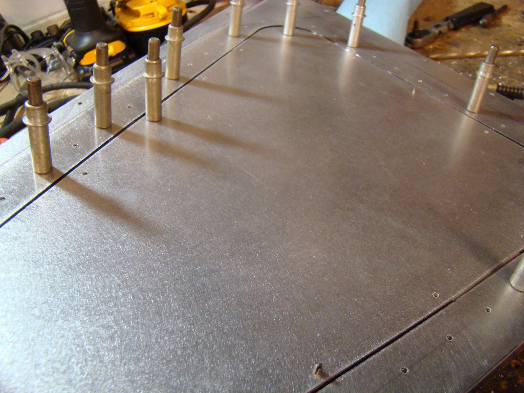
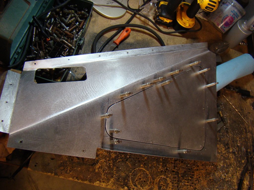
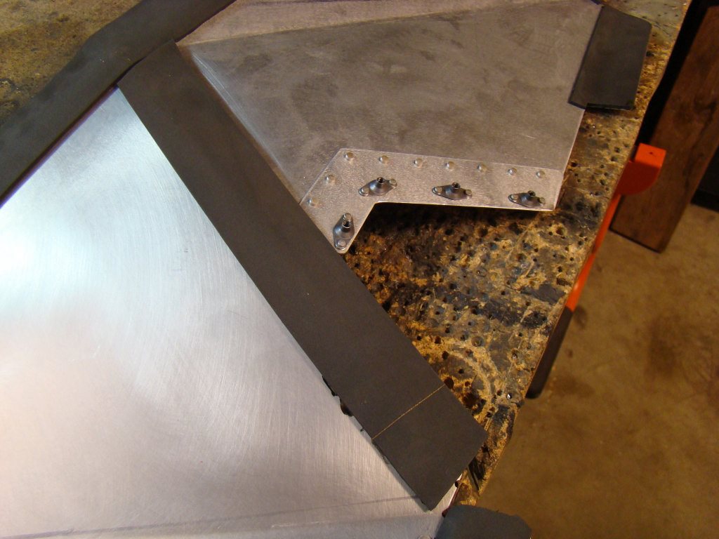
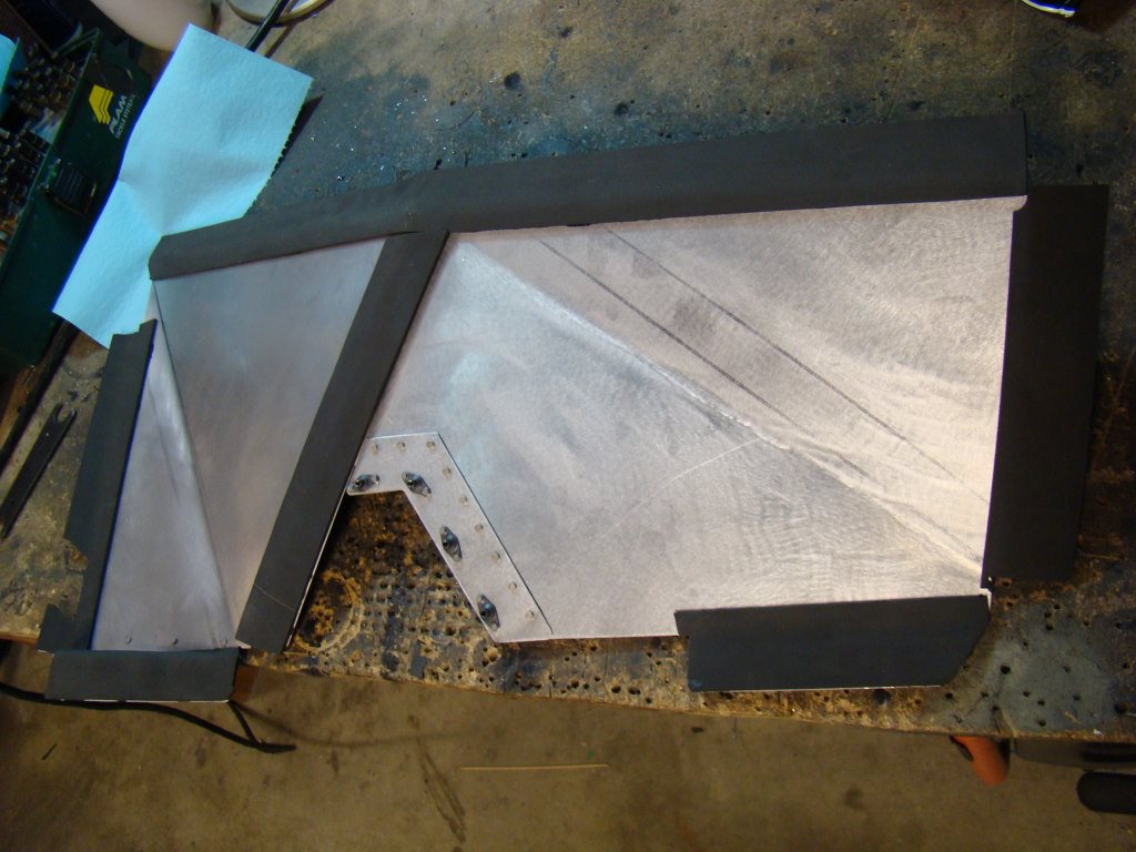
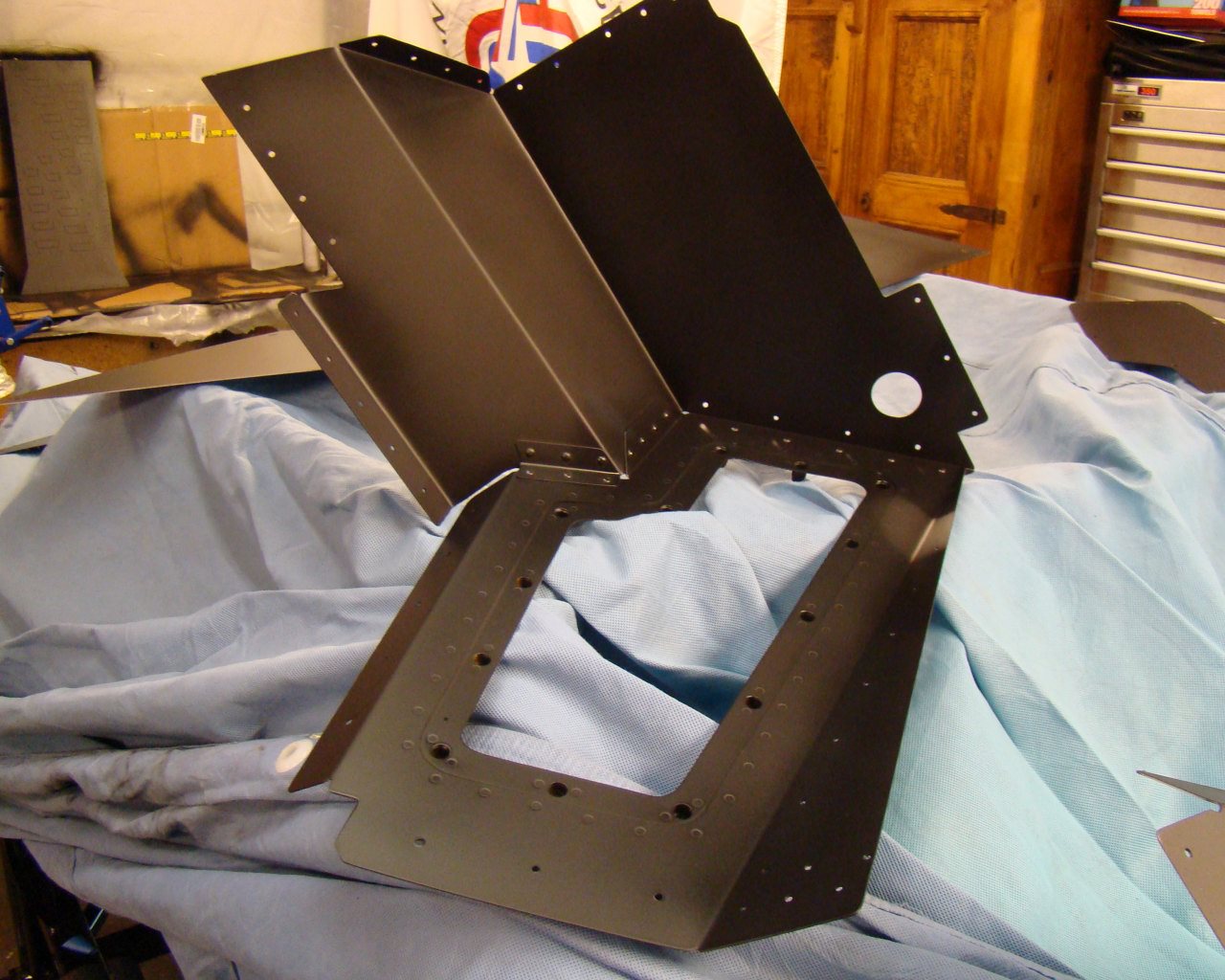
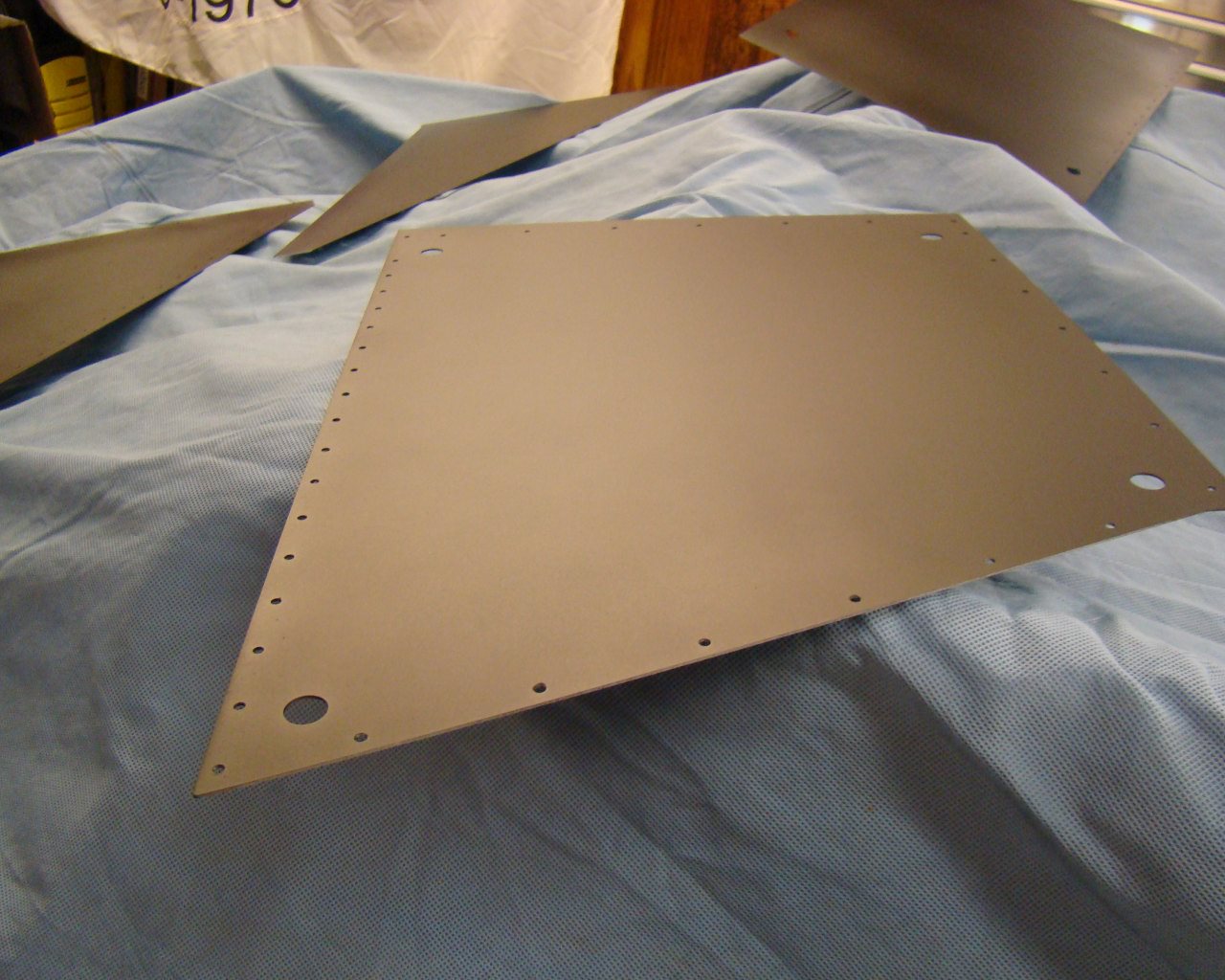
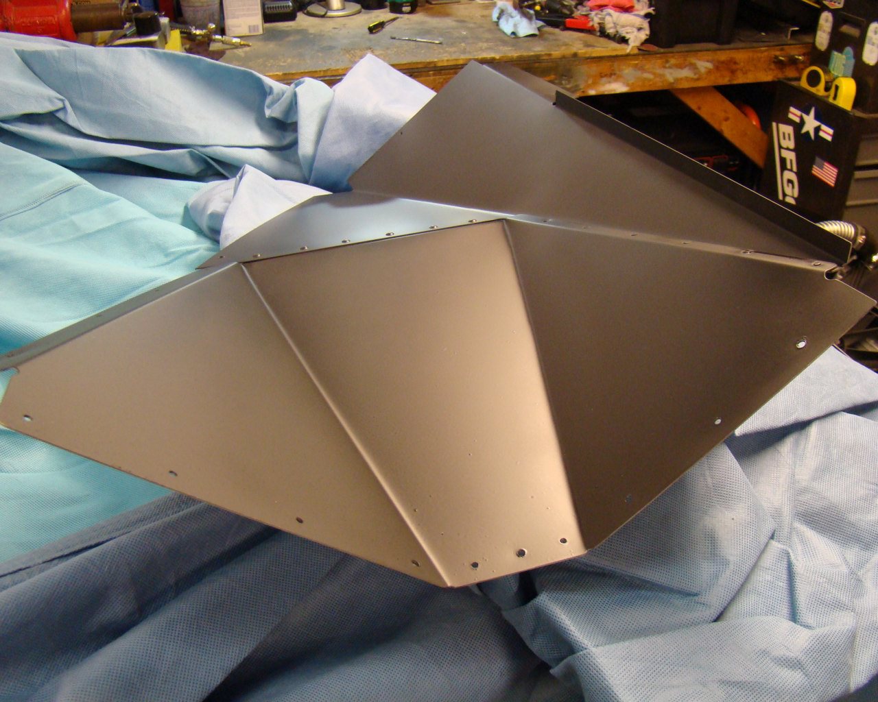
I decided to go ahead with priming all interior aluminum with Easton 2 part Epoxy flat black. This primer is exceptional for aluminum priming and also provides a suitable finish for interior panels that will likely be covered later. These panels will have interior sound proofing applied over them and then the carpet and leather for the final interior finish.
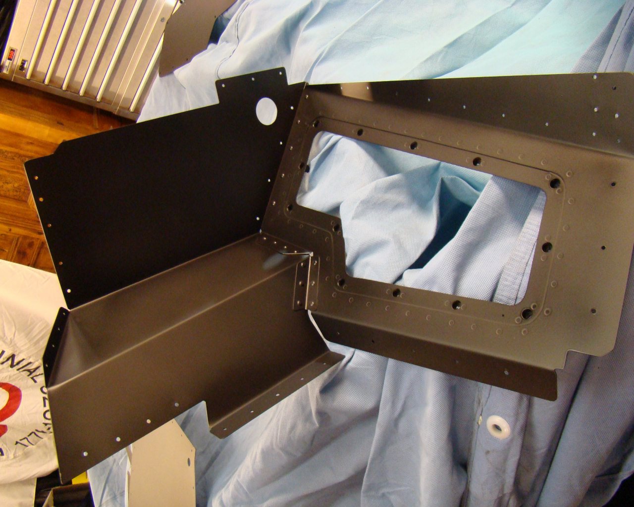
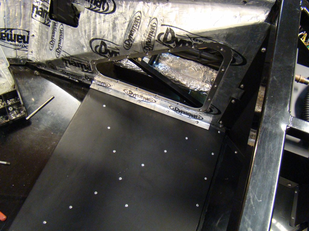
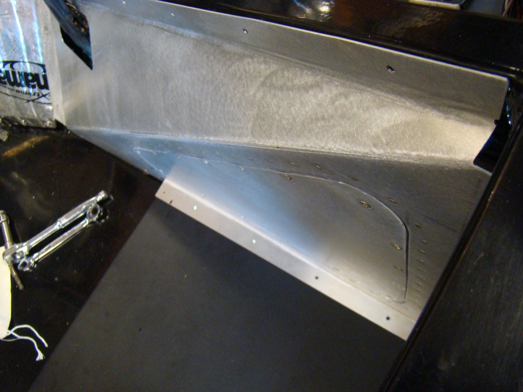
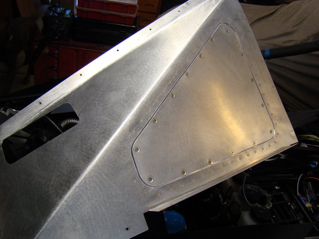
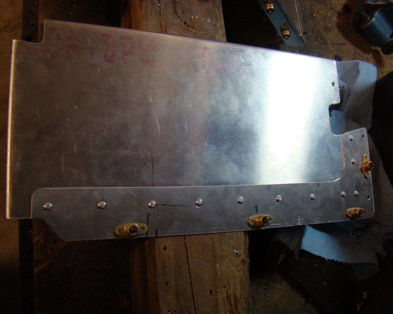
This is the access panel pretty much complete. You can see
the stainless screws around the perimeter. The right side and
forward paneling will be riveted. Notice the screws on the bottom
flanges and vertical frame member. These were installed into
10/32 aluminum rivnuts, similar to the steel rivnuts in the kit but
for 10/32 fine thread aircraft hardware. The 10/32 screws are a
little more finicky because of the finer threads. I just have
alot, so I'm using them. The aluminum rivnuts are fairly
tough but we'll see how long they last. I may replace them
with steel if screws start becoming difficult to remove and replace
over time.
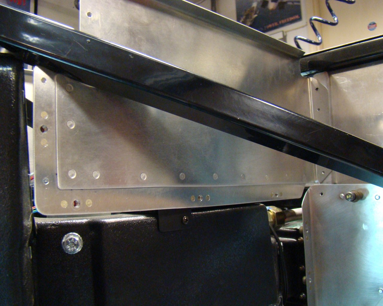
This
shows the doubler on the backside of the passebger A/C evap. access
panel. Notice the small clip attached to the frame.
This secures the aft part of the upper panel and keeps the
nutplates for the screws in the proper orientation. It also
holds the panel firmly in place allowing the screws the be removed
without the panel flexing inboard.
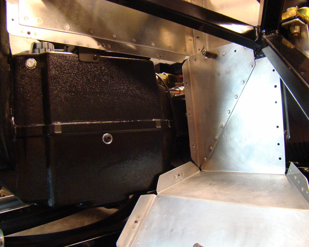
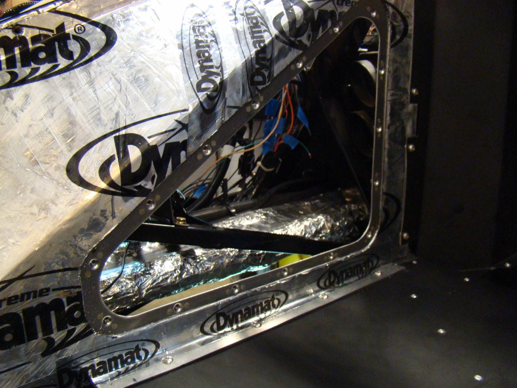
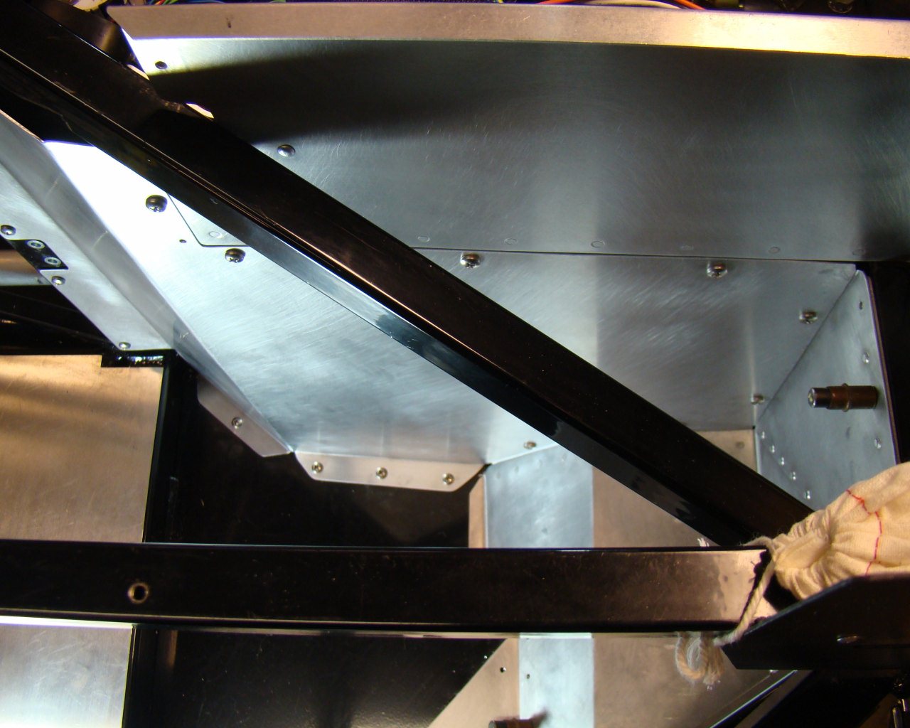
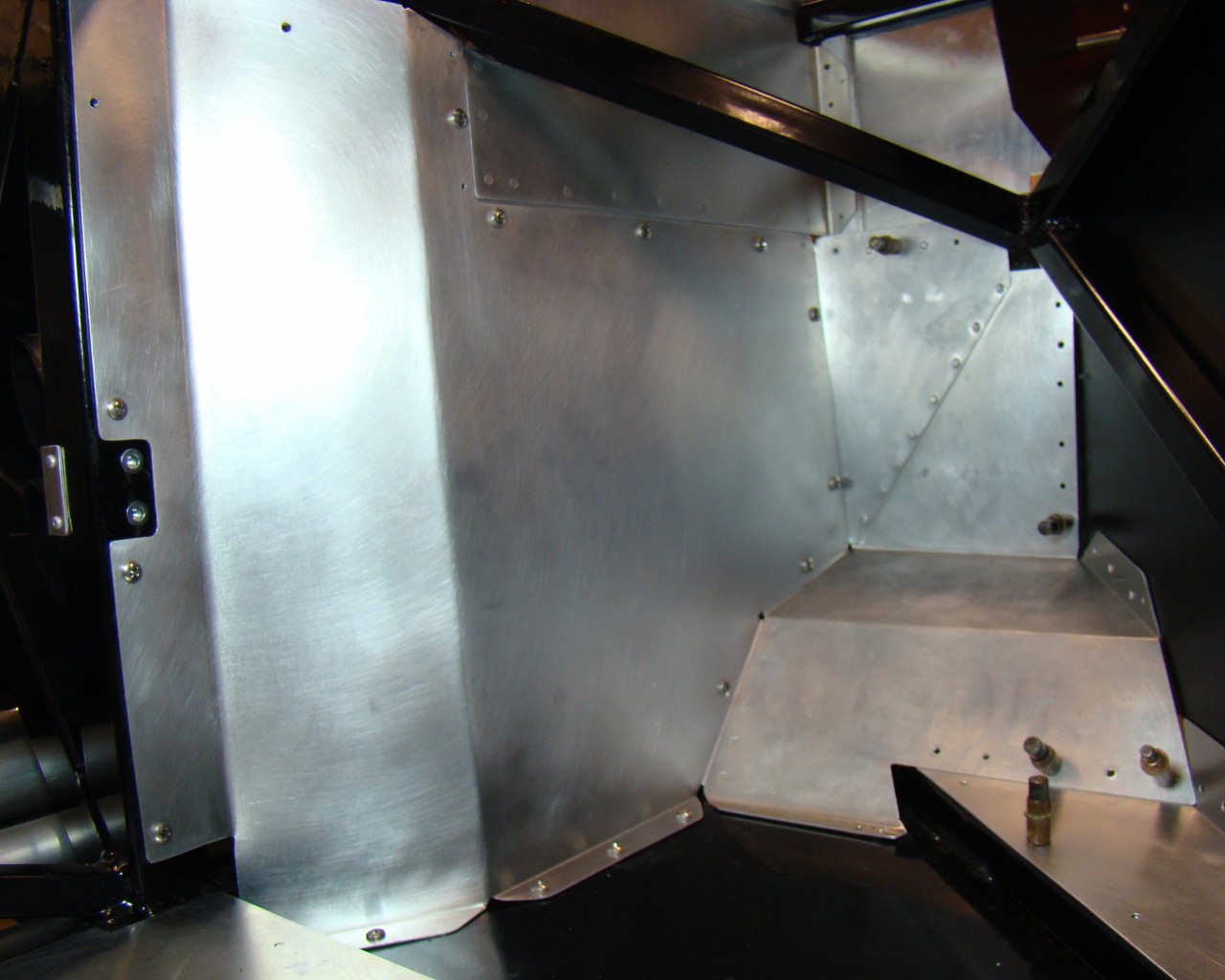
This shows the access with panel removed. Thats alot of room! When installed with the screws, the access panel is as rigid as it would be if it were riveted. The added flanges and solid riveted structure keep things pretty stiff. Notice I kept screws to a minimum. No need to over-do it here because it will create headaches when you have to take the screws out later. The more there are, the more the challenges dealing with them. I used Rivnuts in the floor pan to secure the bottom edge. (Not visible here)
I am a text block. Click on me to drag me around or click a corner handle to resize me. Click the settings icon (it's the left one, looks like a cog) to change this text. You can type new text into me or cut and paste text from somewhere else. Click outside of me when you're done and any changes will be saved.
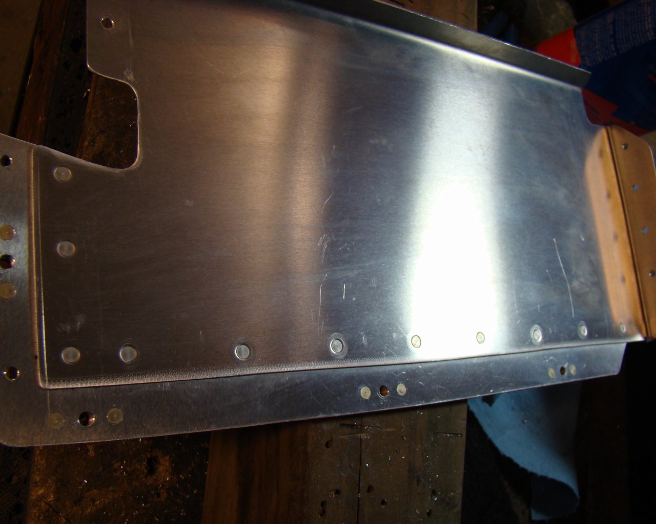
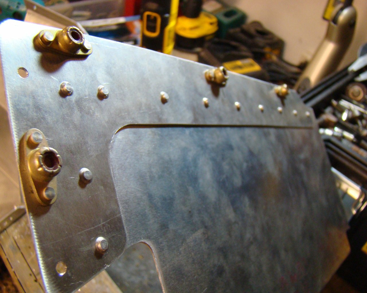
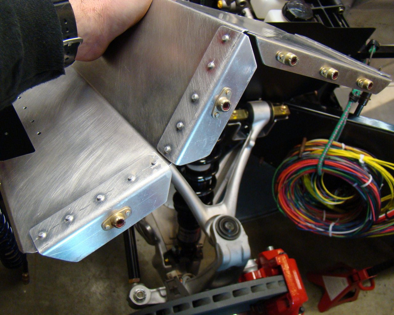
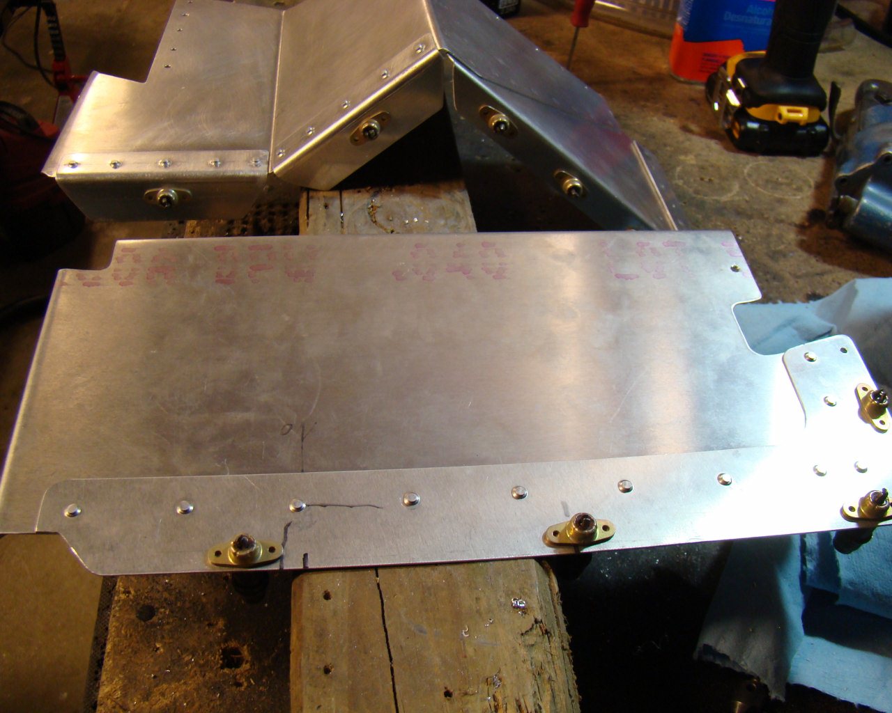
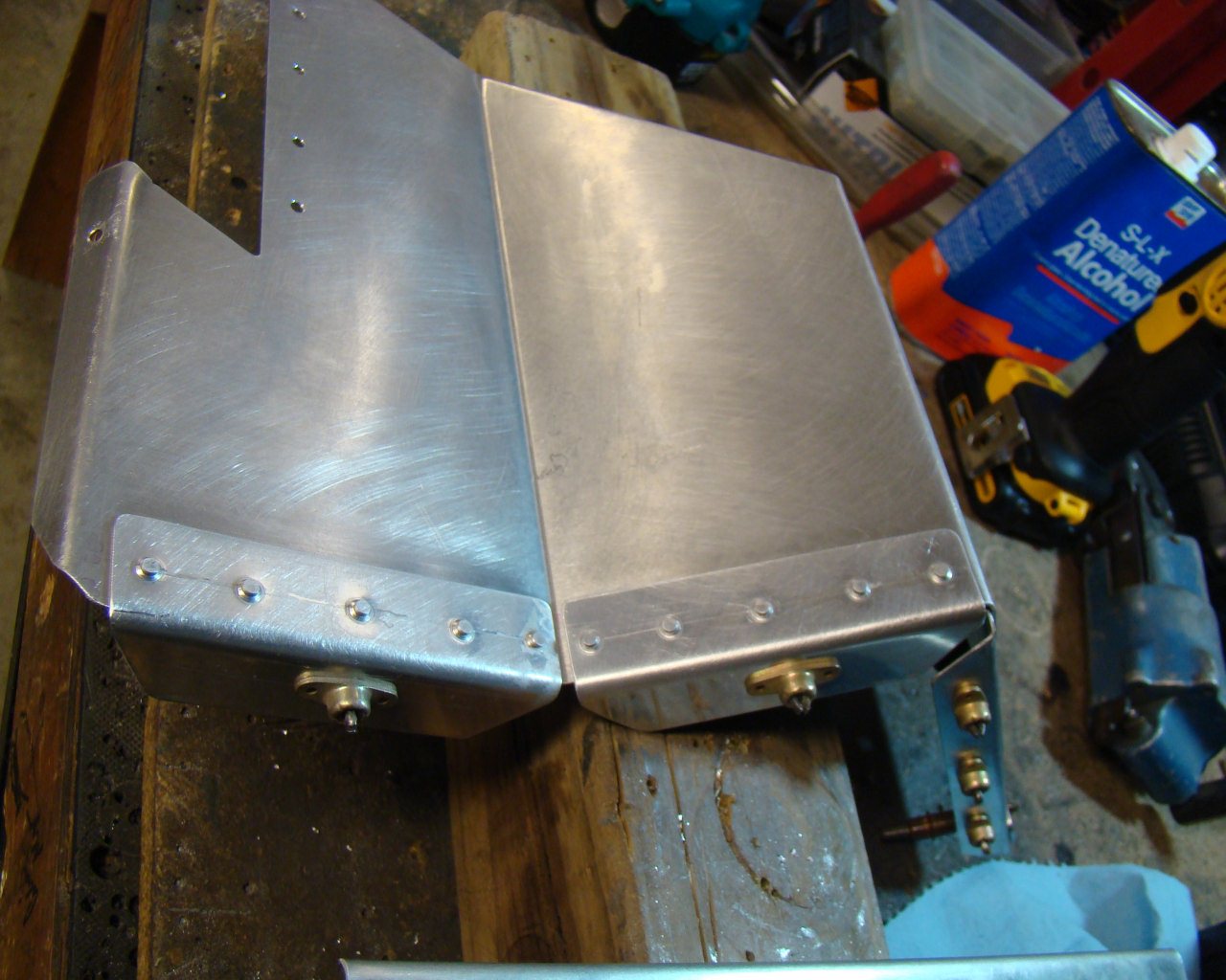
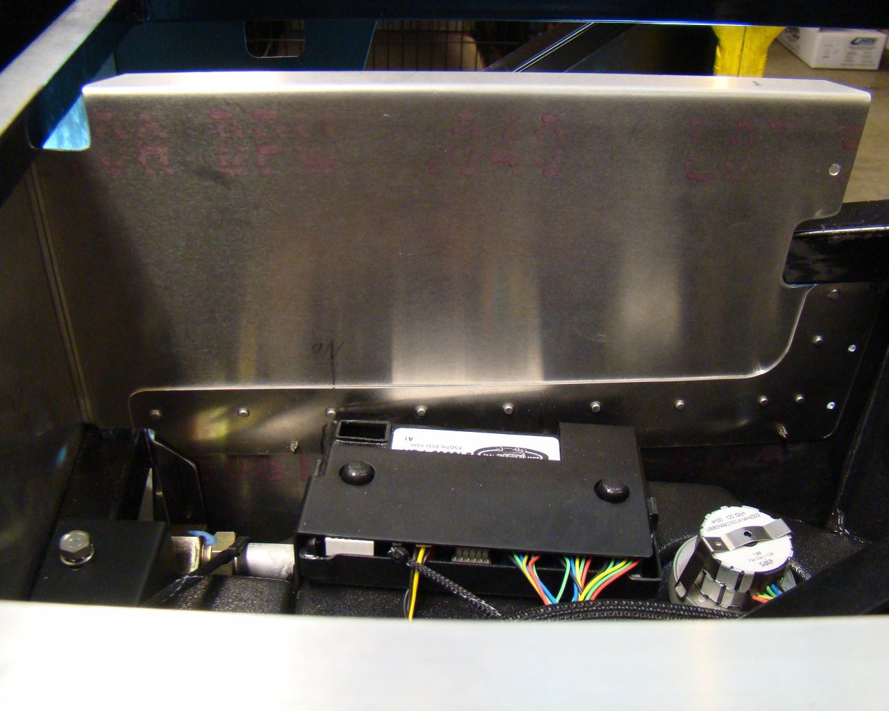
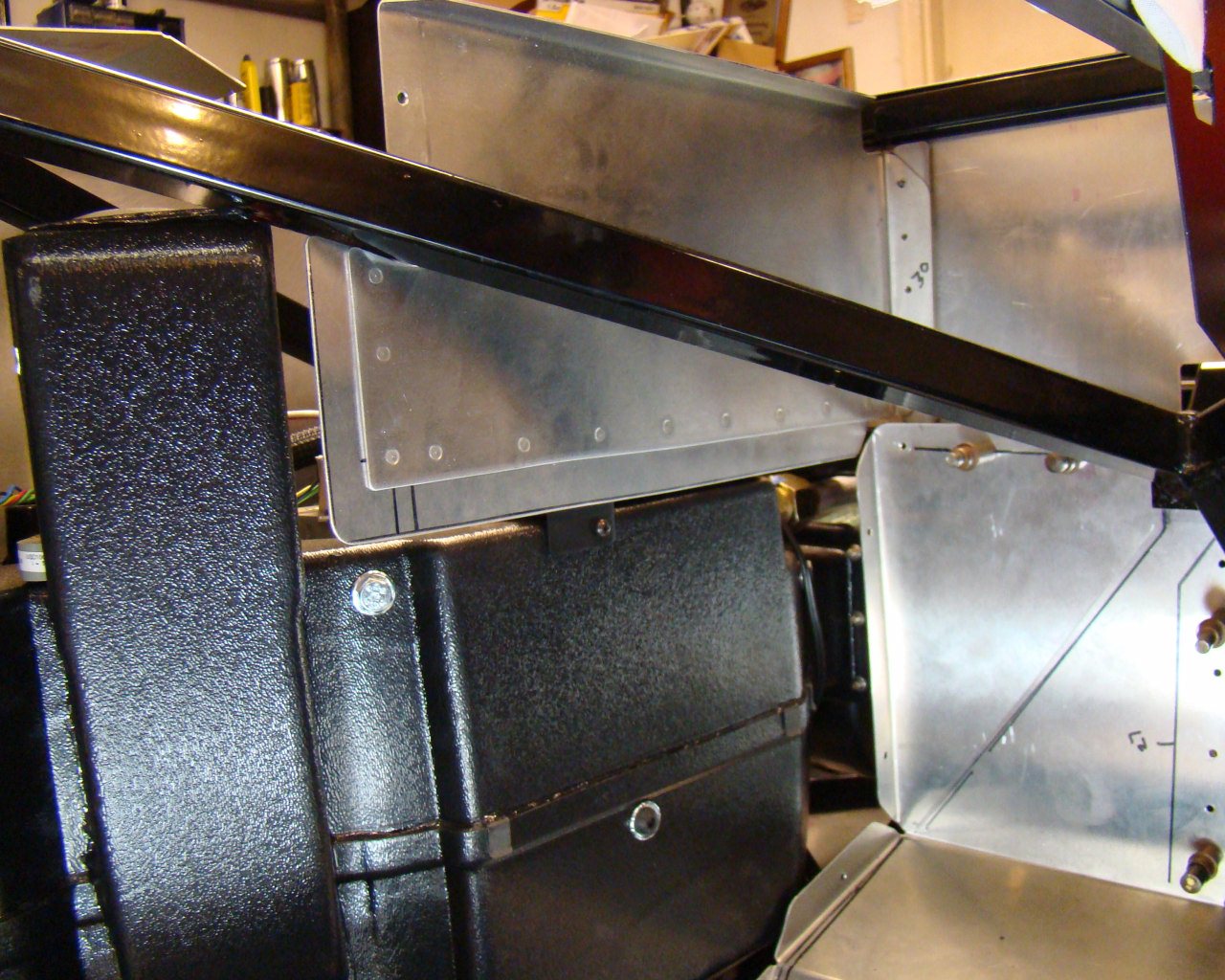
This is a clear shot of the backside with both panels
installed.
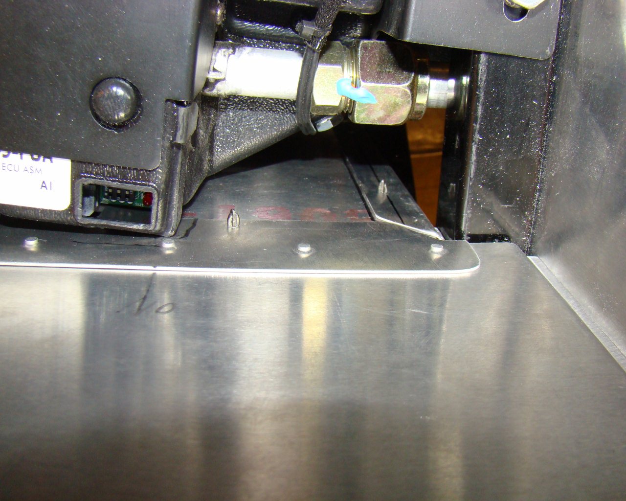
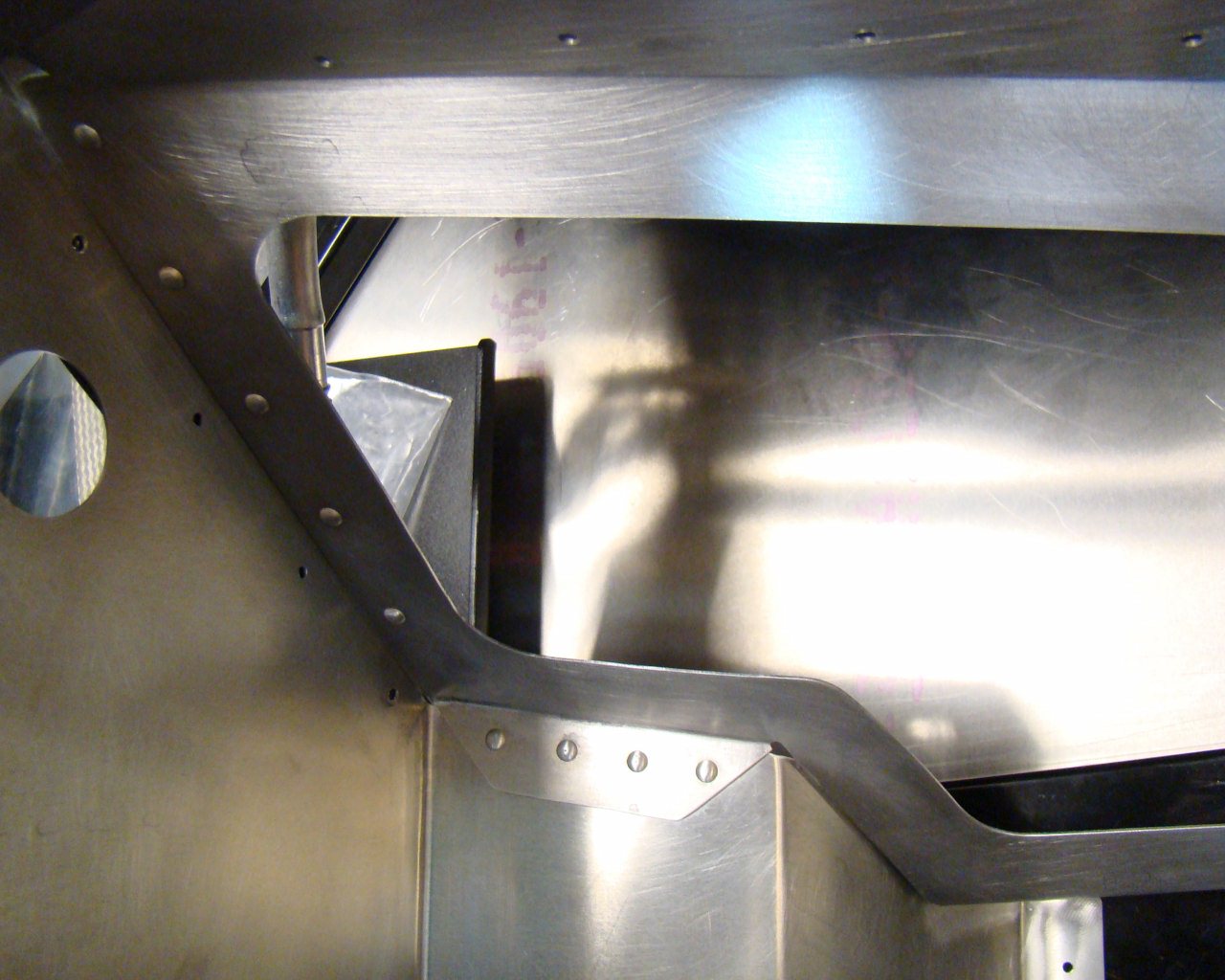
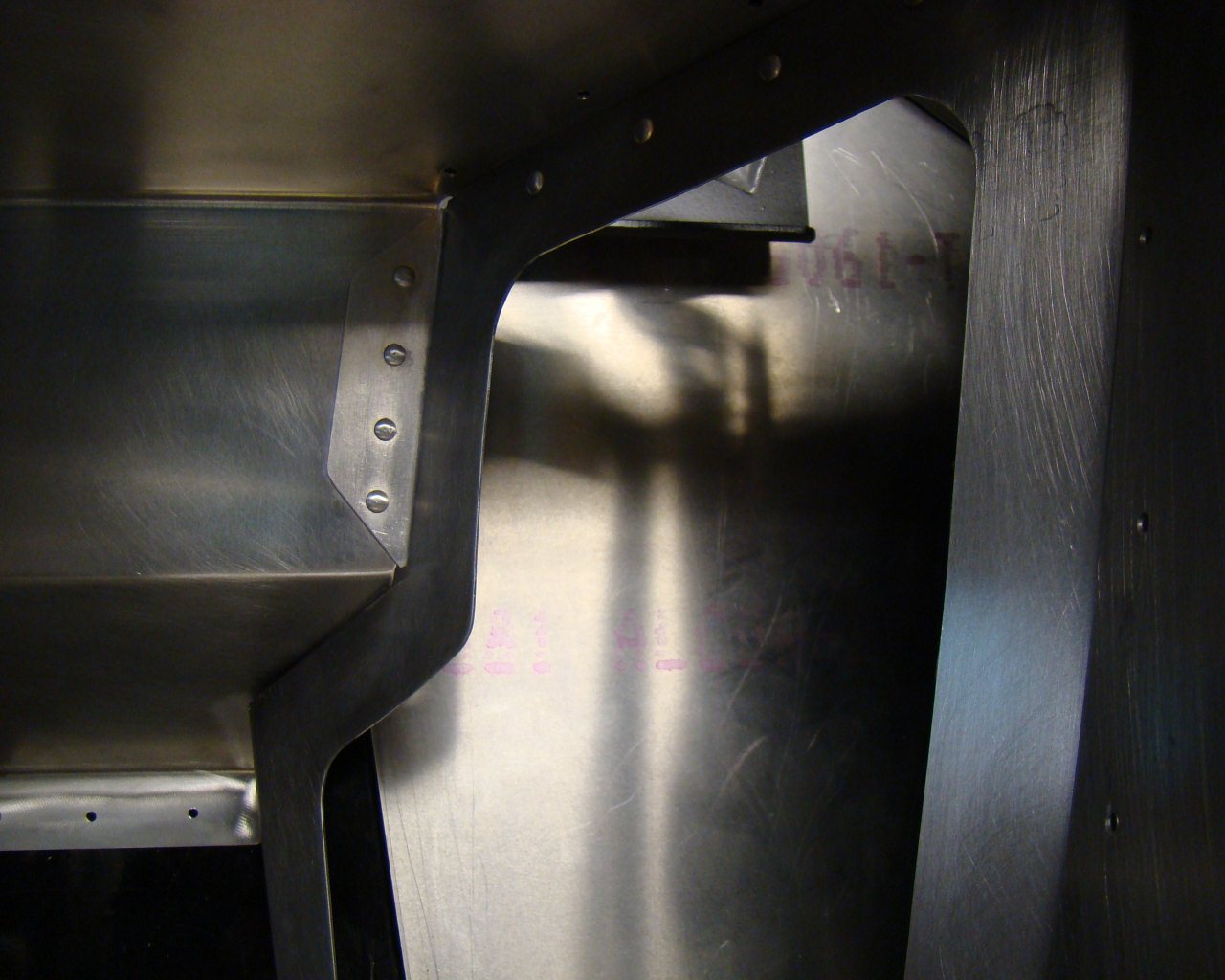
The doubler had to be trimmed at an angle to align and not interfere with the vertical flange of the forward footbox panel.
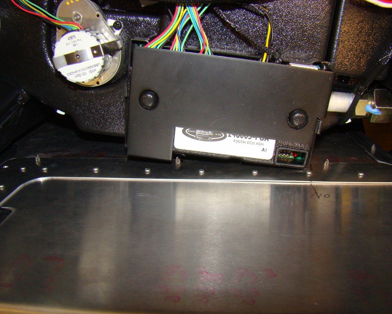
Notice the proximity of the evaporator to the sidewall panel.
This is simply where it sits and represents a space tradeoff
allowing proper leveling, connector access and mounting of the
forward and aft evaporator support angles. Notice the ends of the
clecos and the word "NO" noting where I shouldn't drill screw
holes. I located one screw hole where the maximum space is
achieved (centered in the photo between the two rivets and corner
of the evaporator control box sheet metal
cover).
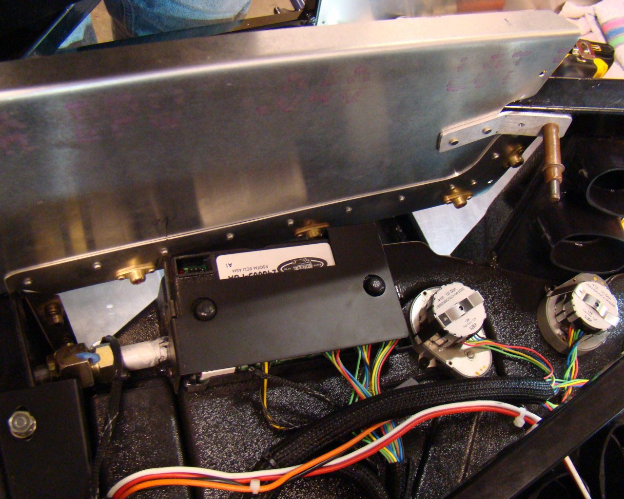
This shows the upper panel that will be permanently
installed. Although the upper area of the Evaporator is not
accesible, the opening will allow additional access to the tunnel
for inspection and some maintenance.
The vertical flanges and fore/aft flanges of the panel that makes up the front of the footbox and attach to the floor and sidewall will also have nutplates for 8/32 screws. They will be tapped to remove the self locking feature for ease of installation and removal of the screws later.
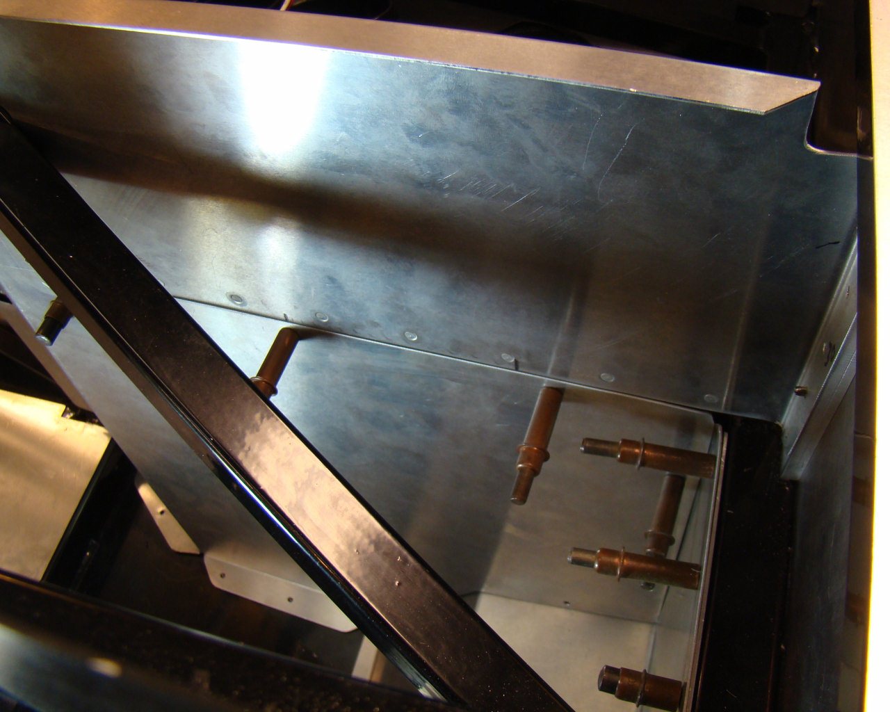
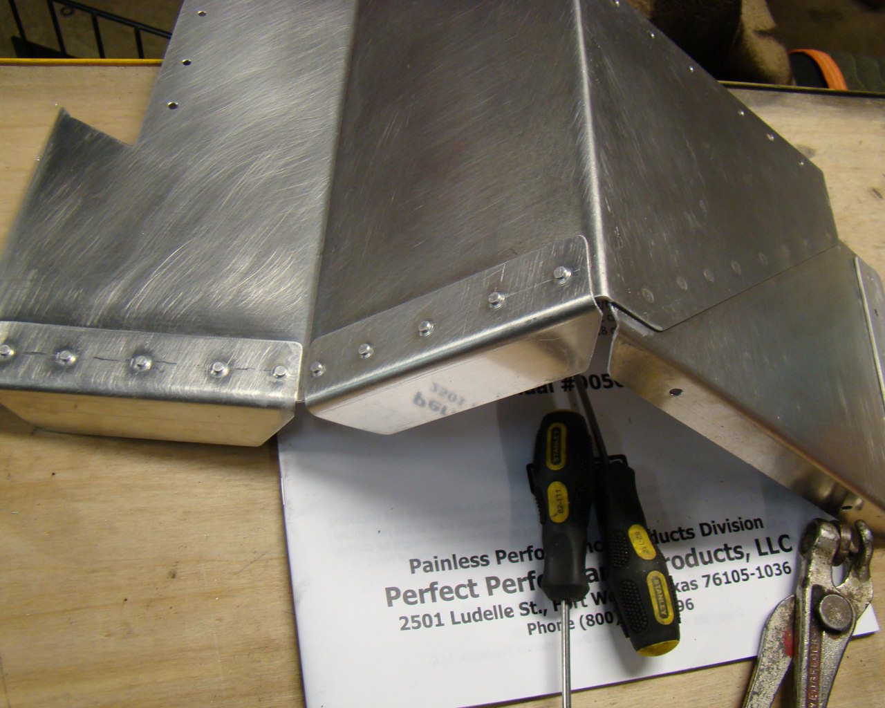
The photo below is looking down at the joint between the split
left passenger footbox sidewall. Screws will be used where
you see the Clecos. This arrangement allows the entire
sidewall panel from the seam - down to the floor to be removed or
installed using screws.
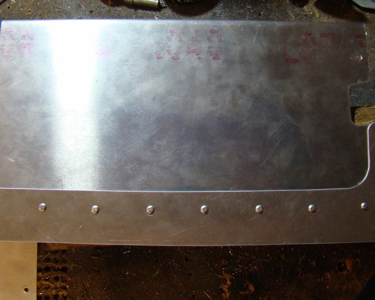
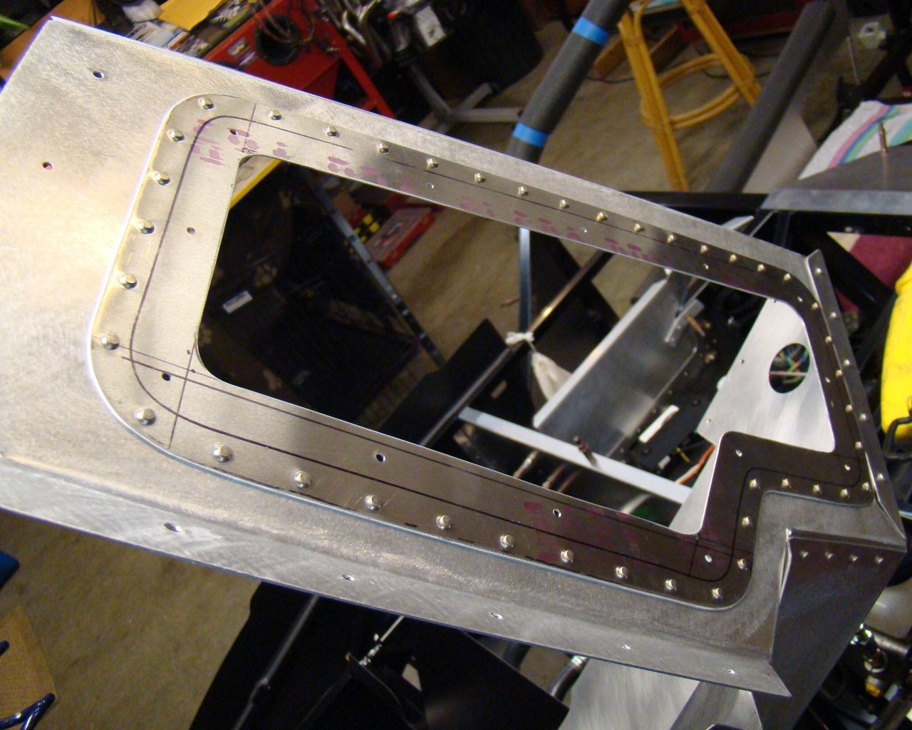
This shows the backside of the doubler.
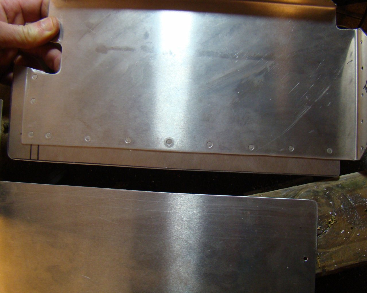
This shows the doubler riveted to the backside of the upper
panel. The exposed lower edge of the doubler will be drilled
along with the panel that sits on it so that screws pass through
and engage nutplates riveted on the backside of the
doubler.
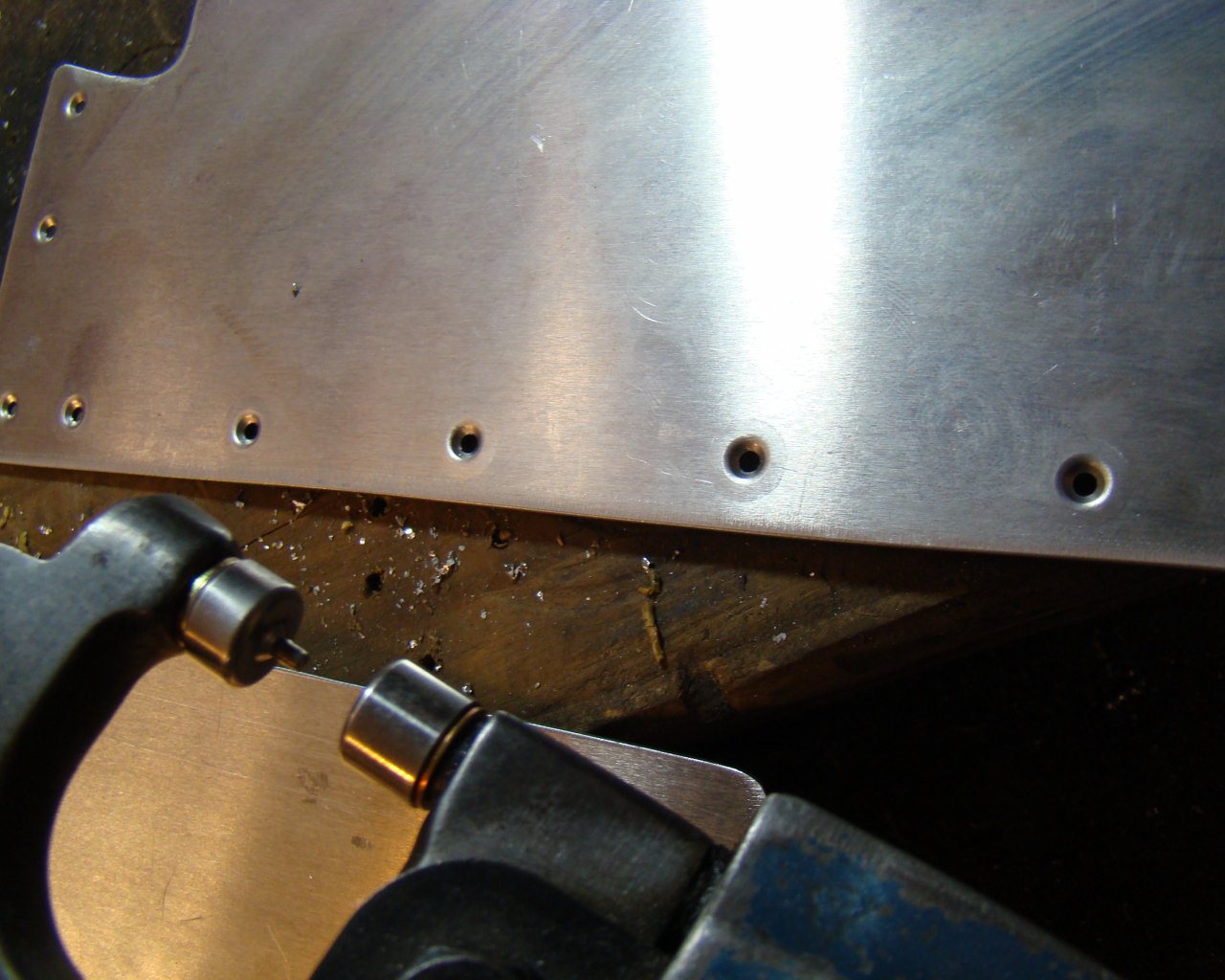
After dimpling
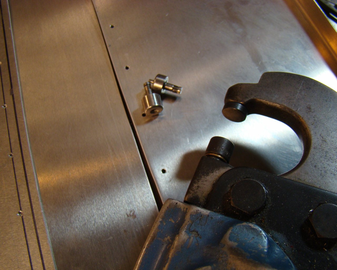
Aircraft tools - This is a photo of a pneumatic rivet squeezer and
3/32 dimple dies. A hand squeezer can be purchased at AT
tools or any common aircraft tool company. Do a search for
aircraft aluminum dimple dies and you can select different sized
dies. These create a perfect countersink in thin metal and
may be spaced in the tool using washers to accomodate different
rivet lengths. Both sheets are dimpled and increase shear strength
while providing perfect engagement of the
sheets.
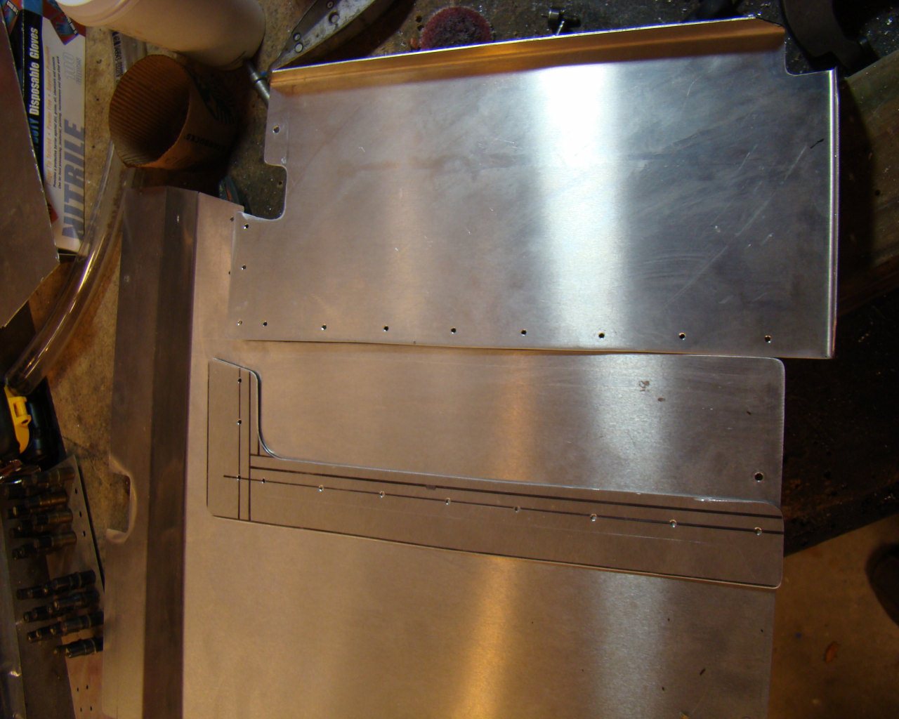
Photo showing passenger left sidewall panel with upper section cut
so that panel becomes two panels fastened by screws that engage
nutplates on a doubler riveted to the upper panel
backside.
WORKING ON THE DRIVERS SIDE SIDEWALL
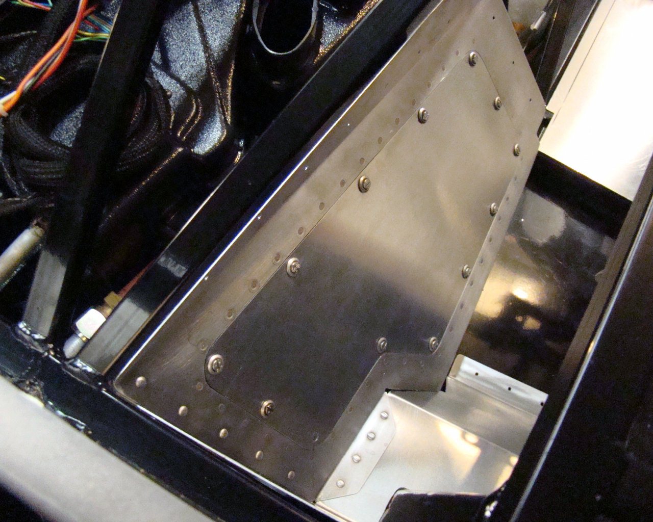
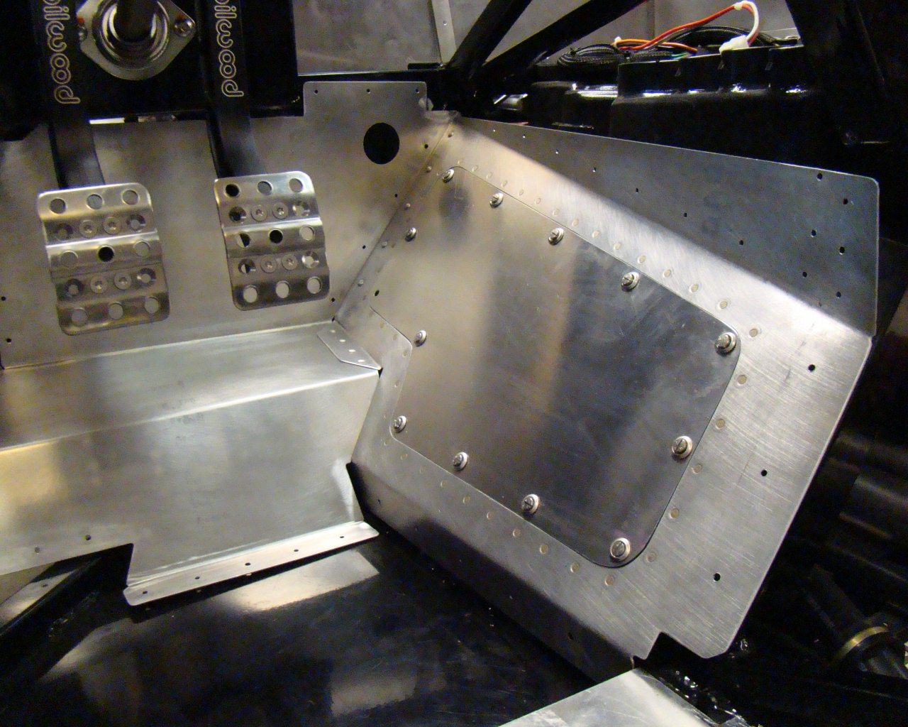
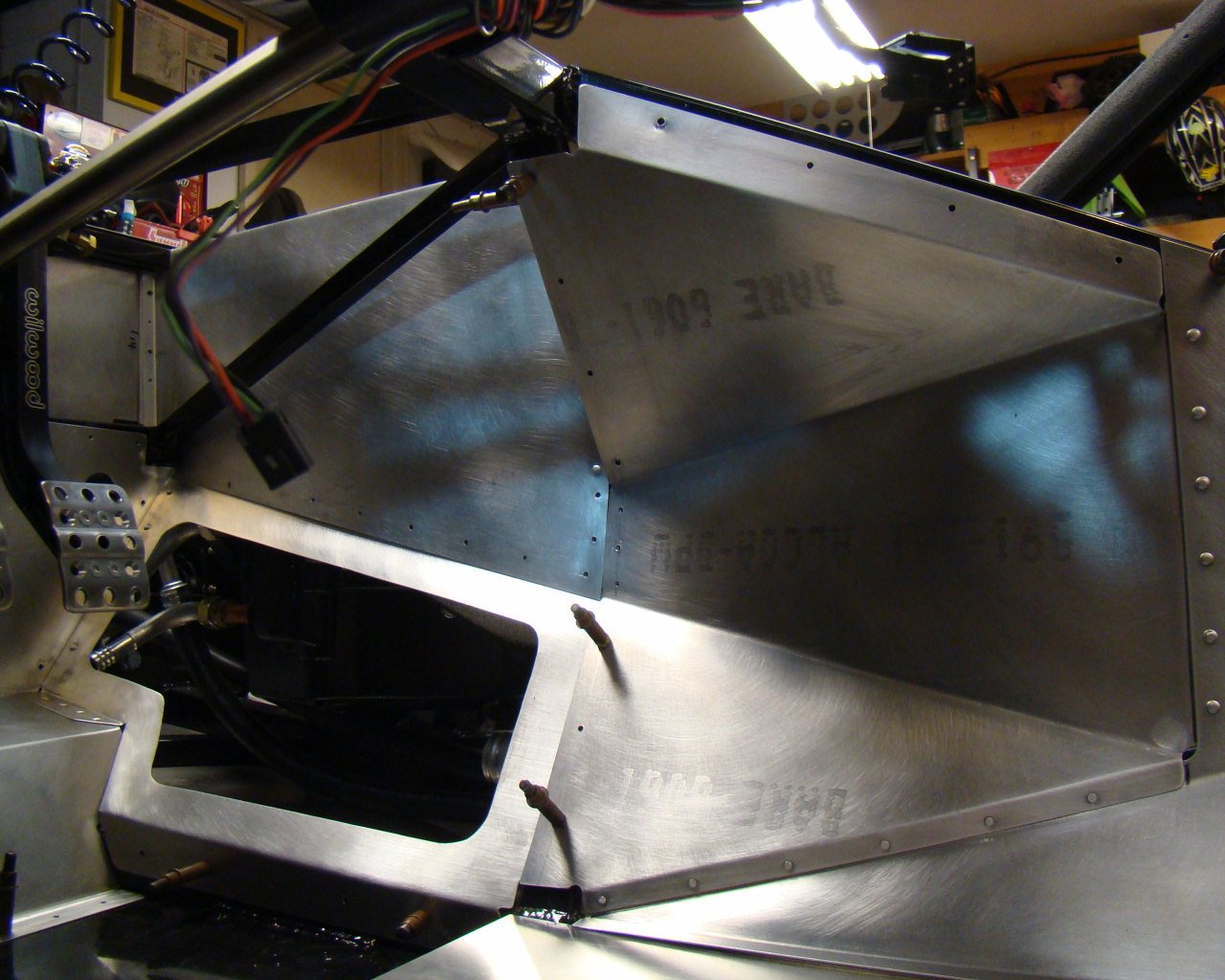
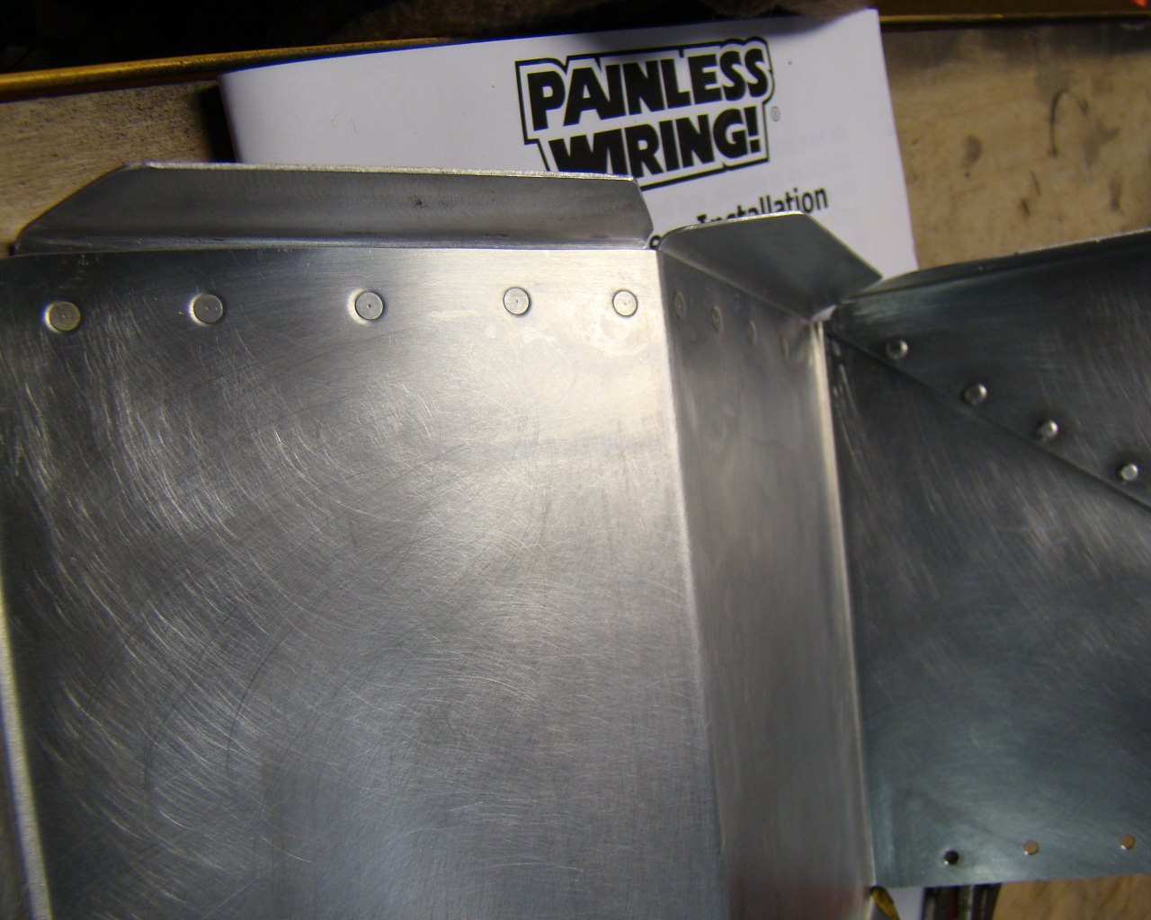
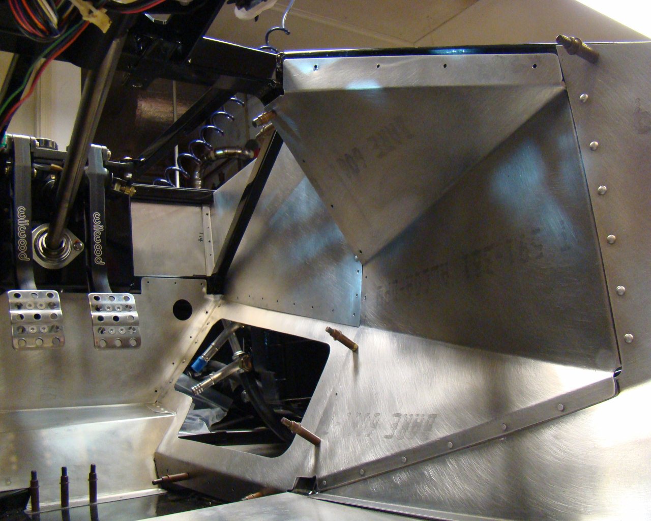
The picture is centered on the forward section of the drivers side
sidewall. The forward panel is riveted (line of solid rivets
to the right) with the lower flange flush riveted with 3/32
countersunk rivets. The head of the rivets on the small lower
flange is on the backside but rests flush on the frame
member. You can see the rivet heads in the below
photos. I will add a strip of thin dampening material or
chafe tape against the frame in that area. I chose not to
rivet the panels against the frame tube here because the assembly
can be secured adequately with screws and rivnuts around the
circumference later. This allows the forward and aft sidewall
assembly to be removed for maintenance. This will provide
access from your knees back to the area just in front of the engine
behind the shifter assembly.
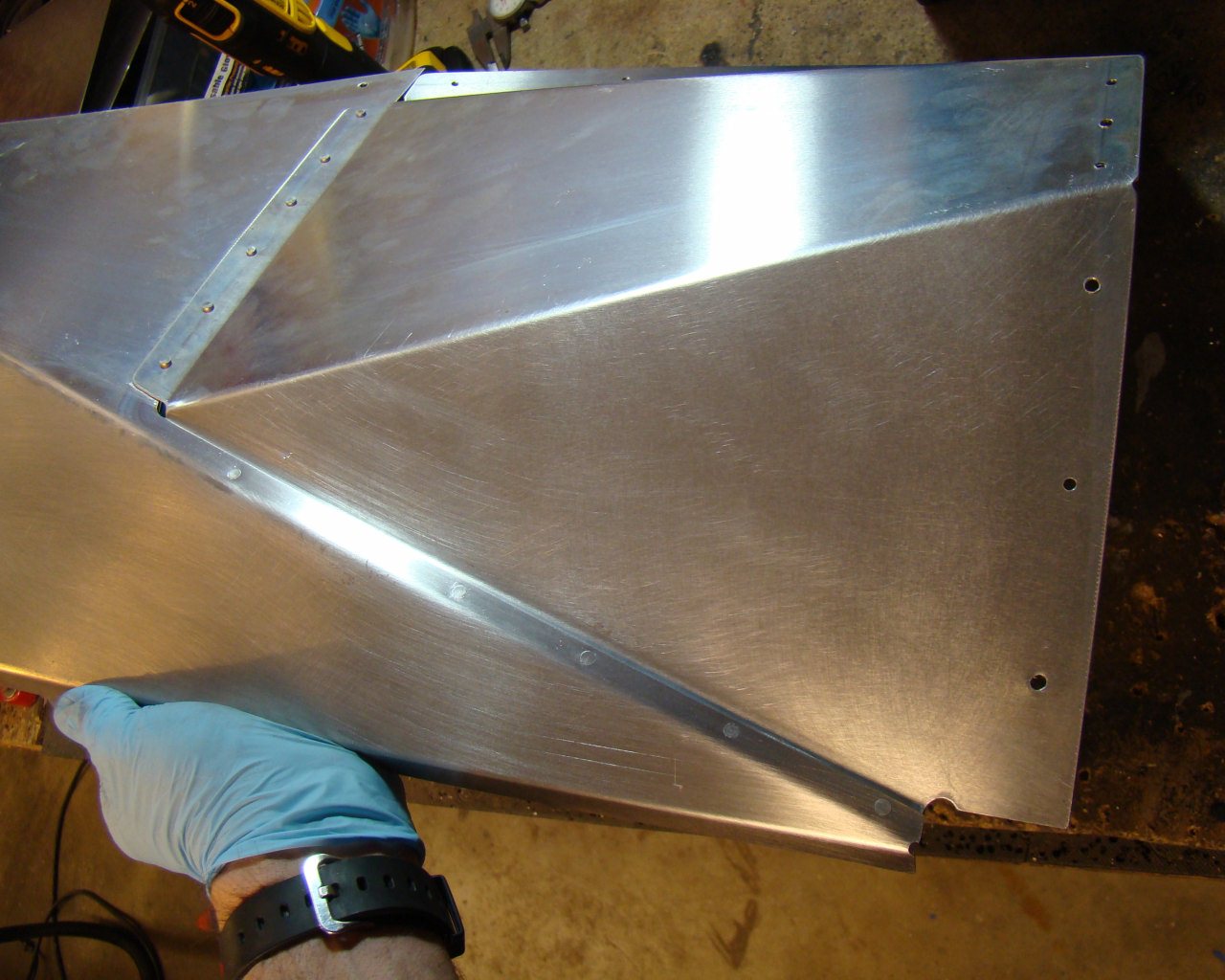
This shows the head of the flush rivets on the back of the panel on
the small flange. The flange can be riveted to the frame if
you desire but use caution when laying out the rivet line and make
sure the panels are positioned correctly with inner and outer
flanges fully engaged. Also be sure the aluminum is firmly
positioned against the frame to avoid your drill walking and
elongating the aluminum. Drilling steel behind aluminum can
cause the drill to walk unless firm steady pressure is used to get
the drill started in the steel.
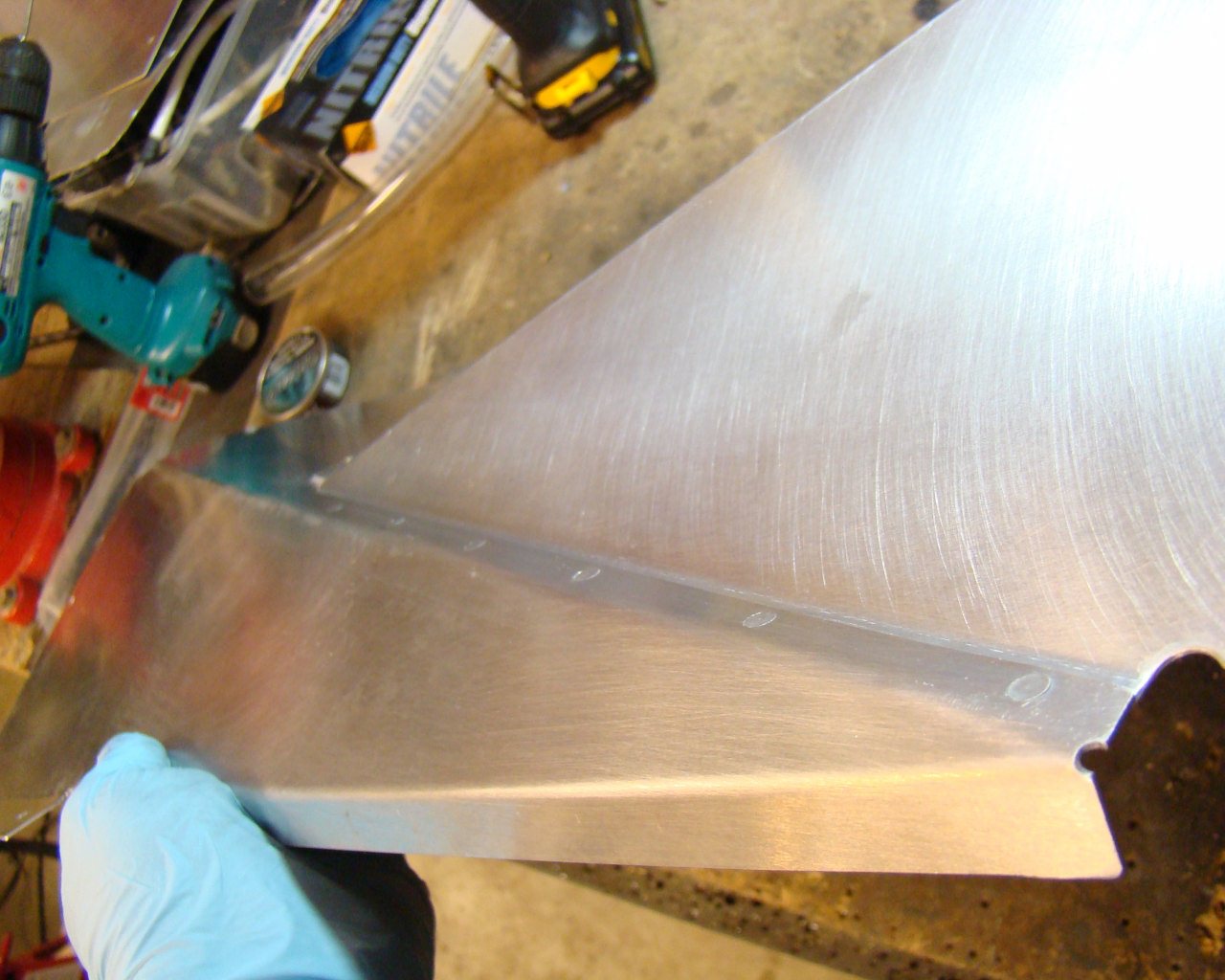
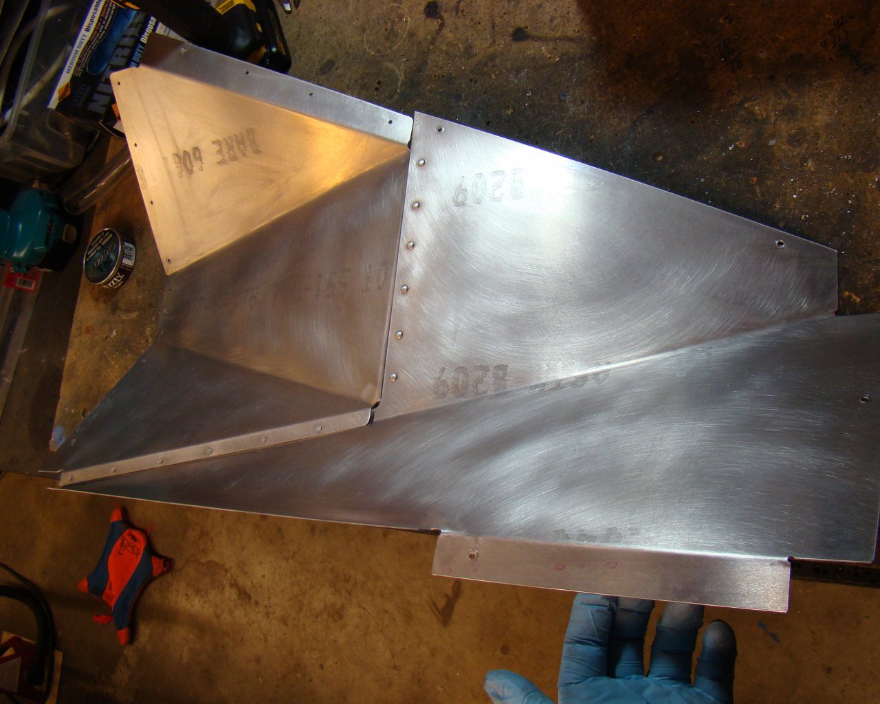
This is what the removable sidewall
looks like. I'm waiting on some rivnuts (Rivet Nuts) to
arrive (8/32x.020 - .100 grip) before locating the screw holes. I
found similar rivnuts at Jay-Cee Sales and Rivet
Inc.
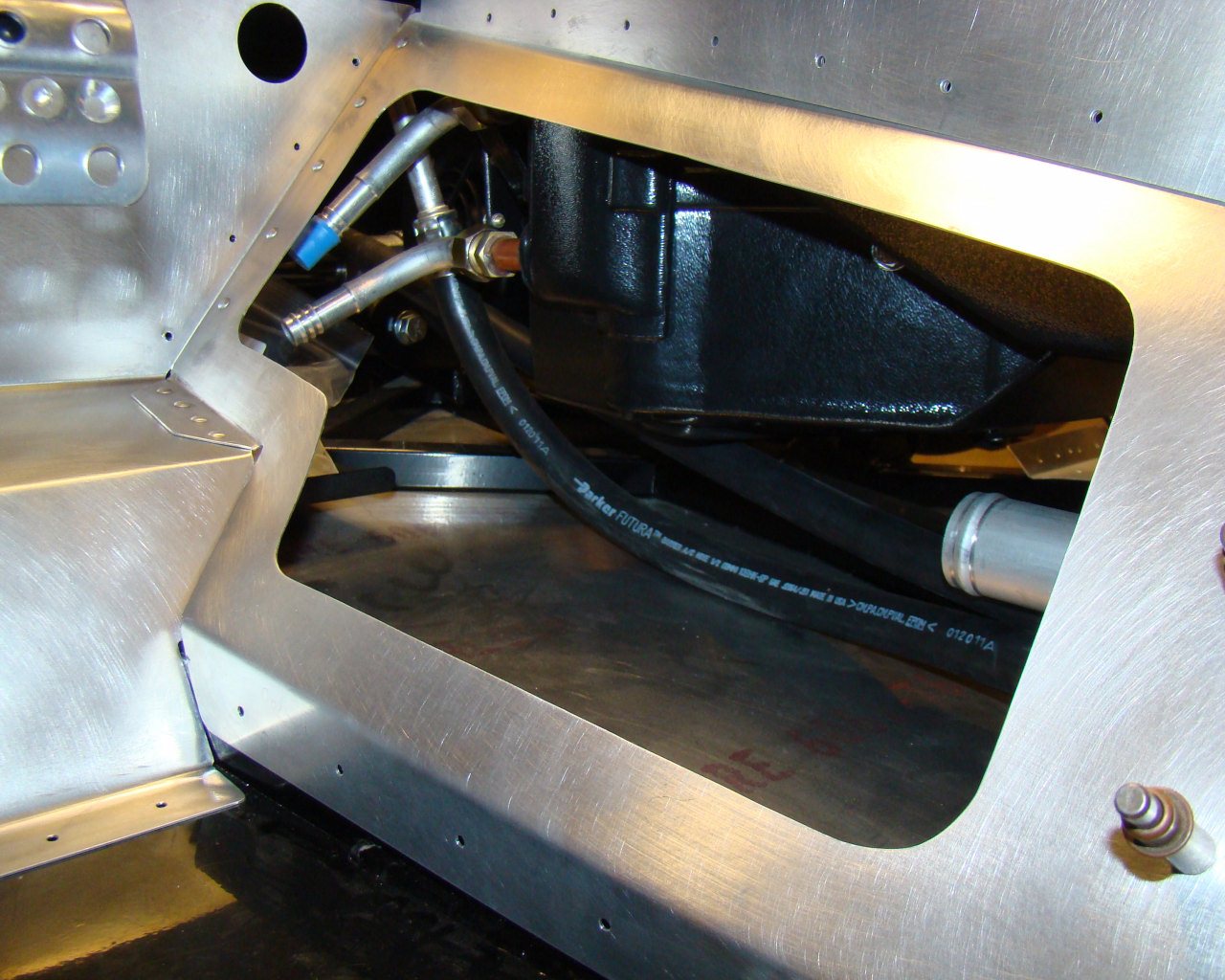
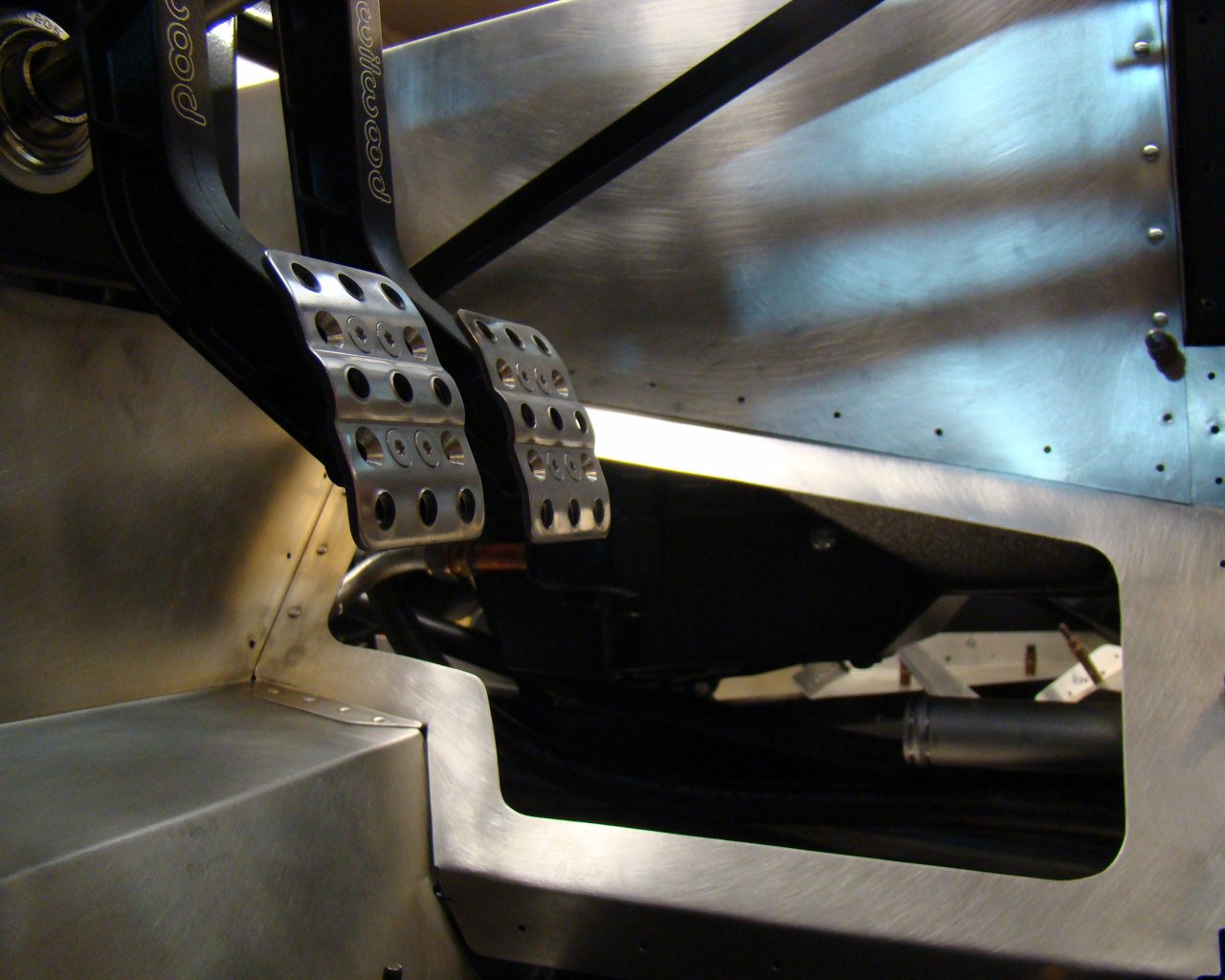
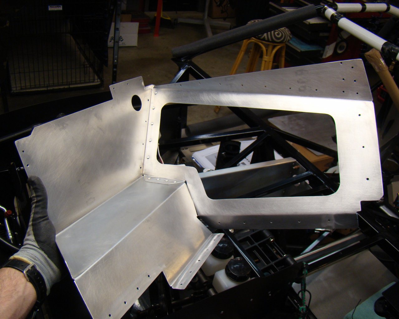
Notice the solid aircraft rivets used in some areas. This section can now be slid into place as an assembly - after fabricating the access panel and doubler.
Some of the metal actually
fits without preload if you bring the flanges to the outside.
When they were placed in the car by Factory Five, some of the
overlaps caused the radius of many panels to "jam" into the joining
piece. This isn't good and can cause stress in these
areas. Under extended vibration, they can crack. You should
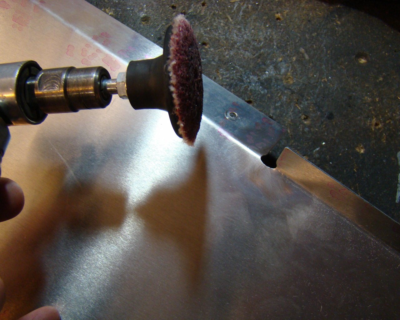
open up some of the corners and relieve areas where possible by
removing some of the metal with a rotary file. Clean up the
edges in the radii to prevent cracks.
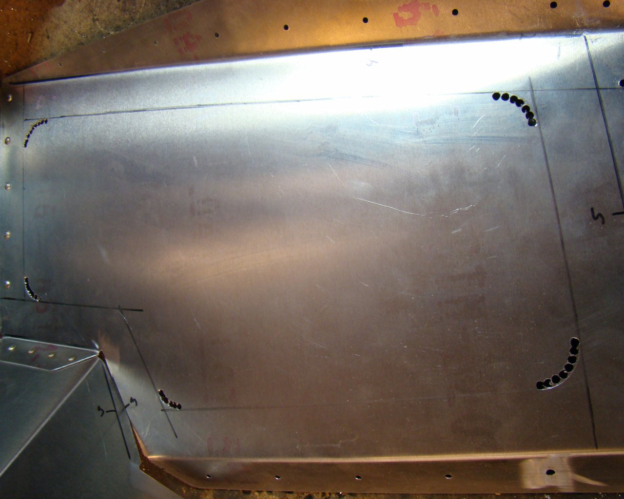
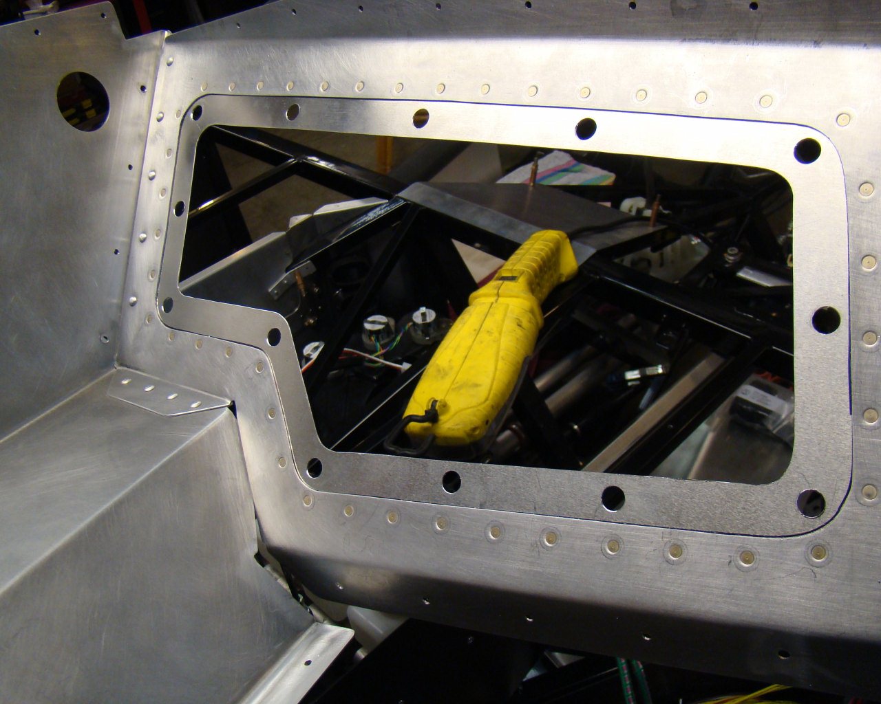
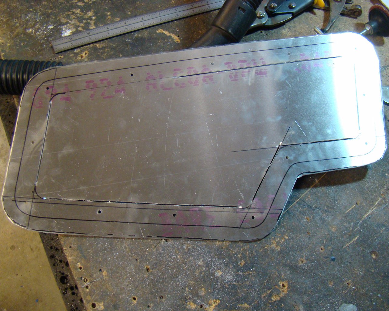
Here I've laid out an access panel cutout measured in approximately 1.5 inches from all adjacent panel walls and bends. The radius at each corner is 'chain' drilled and the straight lines are cut with a 20,000 RPM thin cutting wheel on a pneumaticdie grinder.
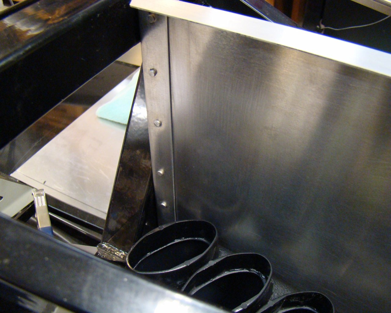
The angle attaching the drivers side footbox wall can be solid riveted (or pop riveted) as desired prior to actual installation in the car. Its fairly easy to manipulate both this assembly and the riveted sidewall / lower forward foot box wall assembly into their respective locations. Thats two assemblies instead of three panels and the angle. By the way, the angle is the one that has the appx 1.5" hole cutout facing fore/aft.
