FUEL
SYSTEM
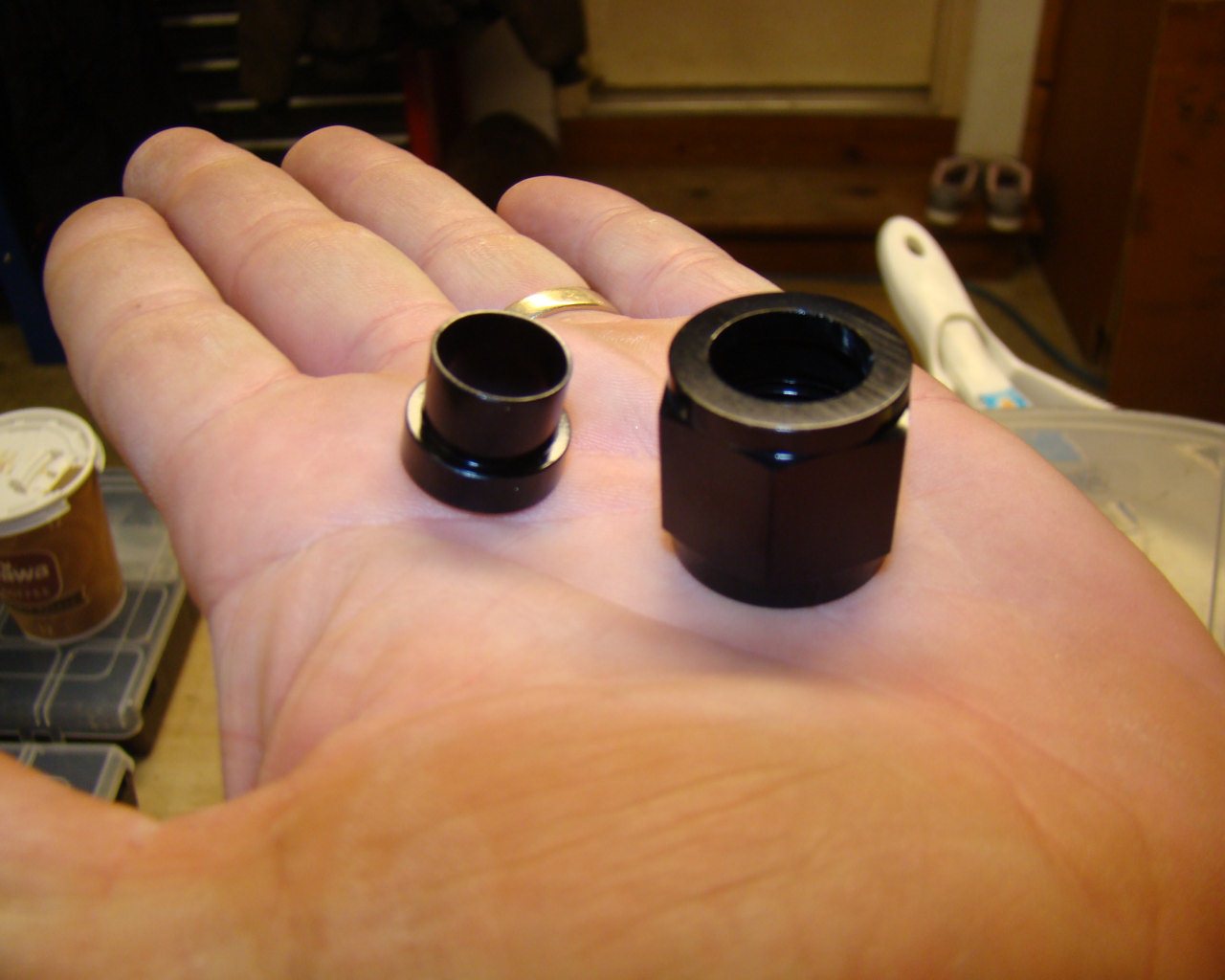
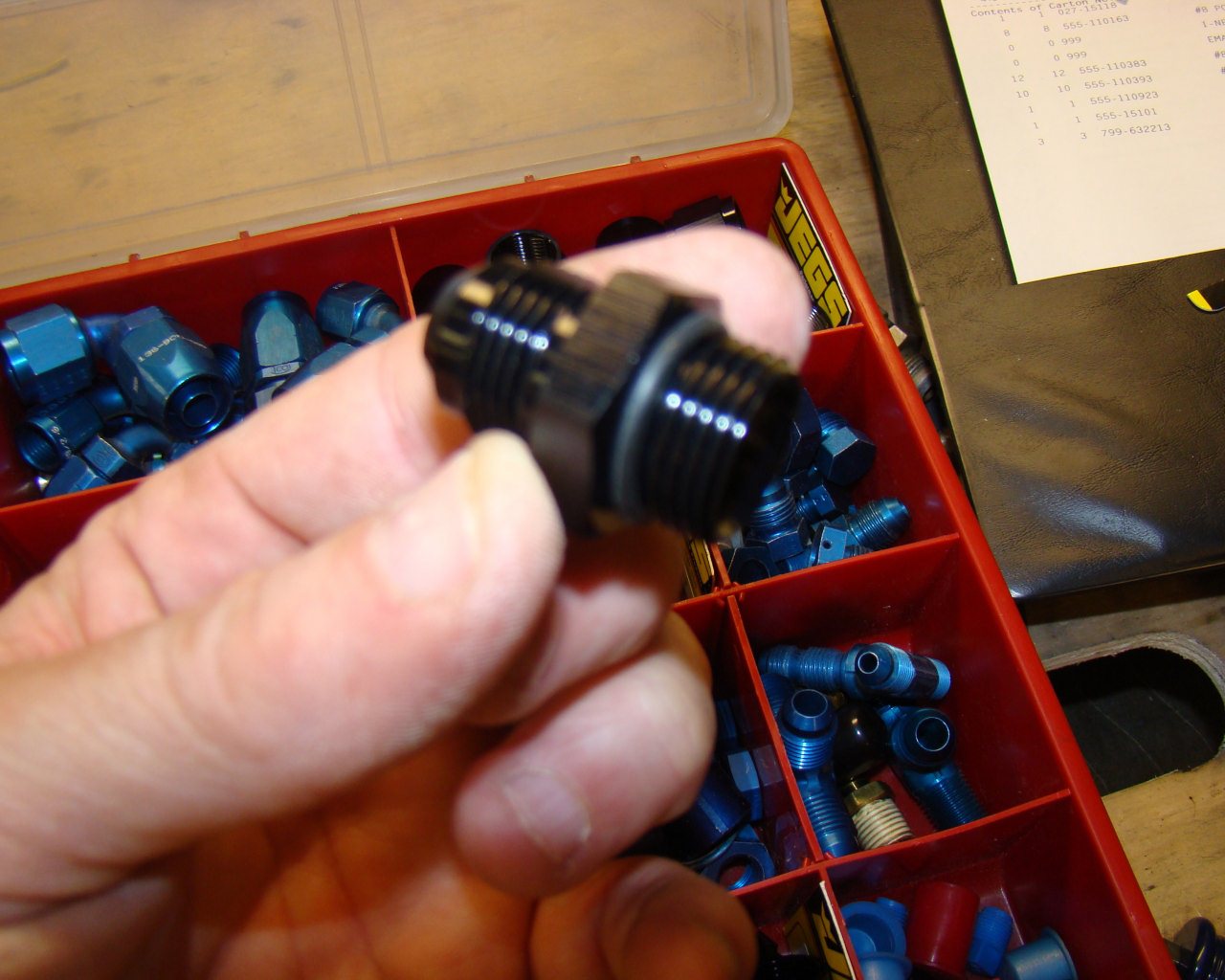
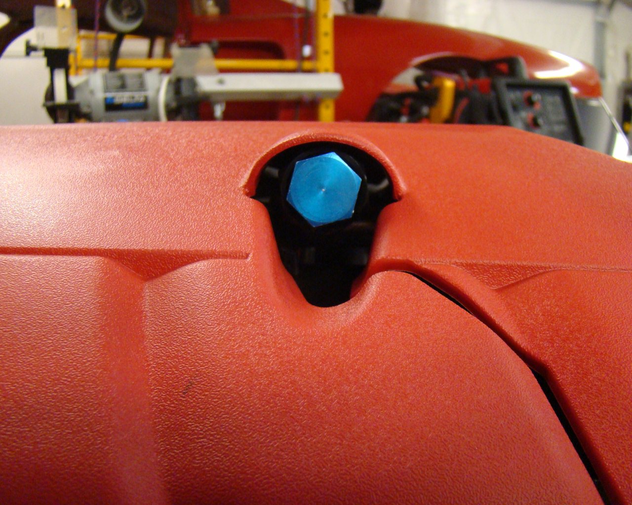
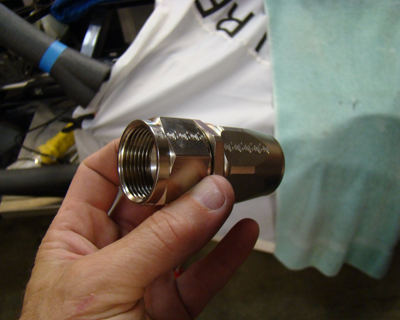
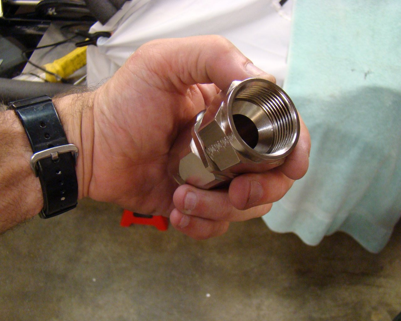
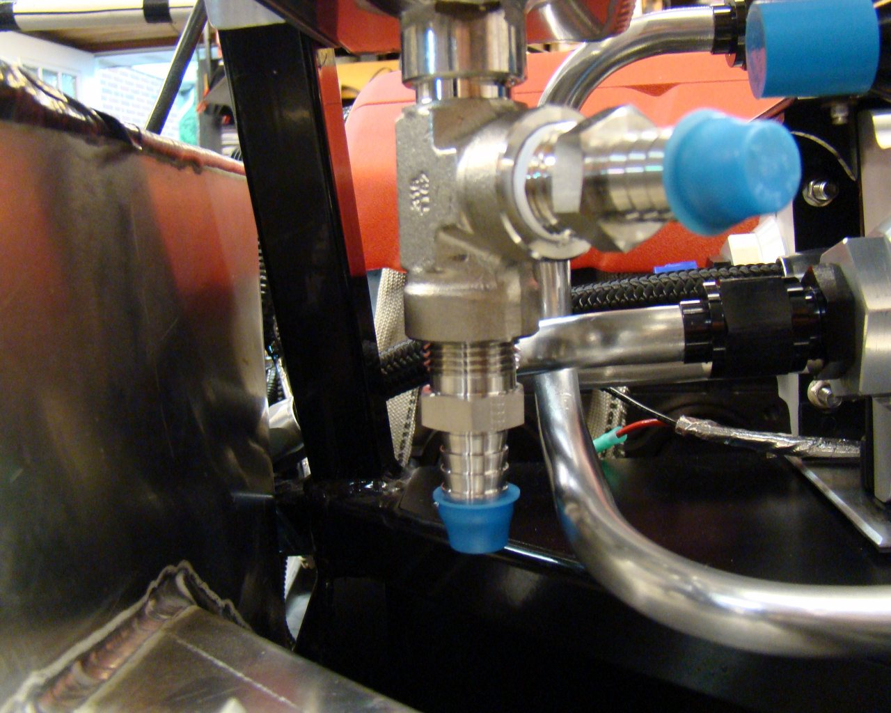
3/1/13 - I've managed to get most of the fuel system parts and will start laying out the fuel lines once the engine is in the car. I've decided on the Holley billet puel pump, regulator, pre and post filter and "Russell" high pressure fuel gauge. For the lines, I'll be using "Pro Flow" black nylon braided AN-8. I'll likely do some hard line plumbing for the regulator, pump and filters as a system. The feed line to the engine will be a hose. Each of the Holley components require AN -8 adapters with the O-Rings as shown in the below photo to the right. The hard lines require the flared sleeve and union which will be installed on custom bent 1/2" aluminum tubing. The hose going to the engine will engage a -8 AN adapter threaded into an "Aeroquip" LS fuel line - to - AN-8 adapter, (Blue AN Cap in the photo). I'll take some pictures of the components and list the model numbers on the next update.
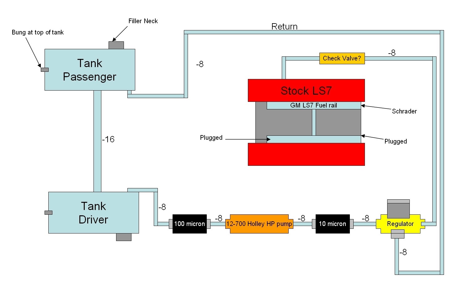
The below illustration is the current fuel system routing.
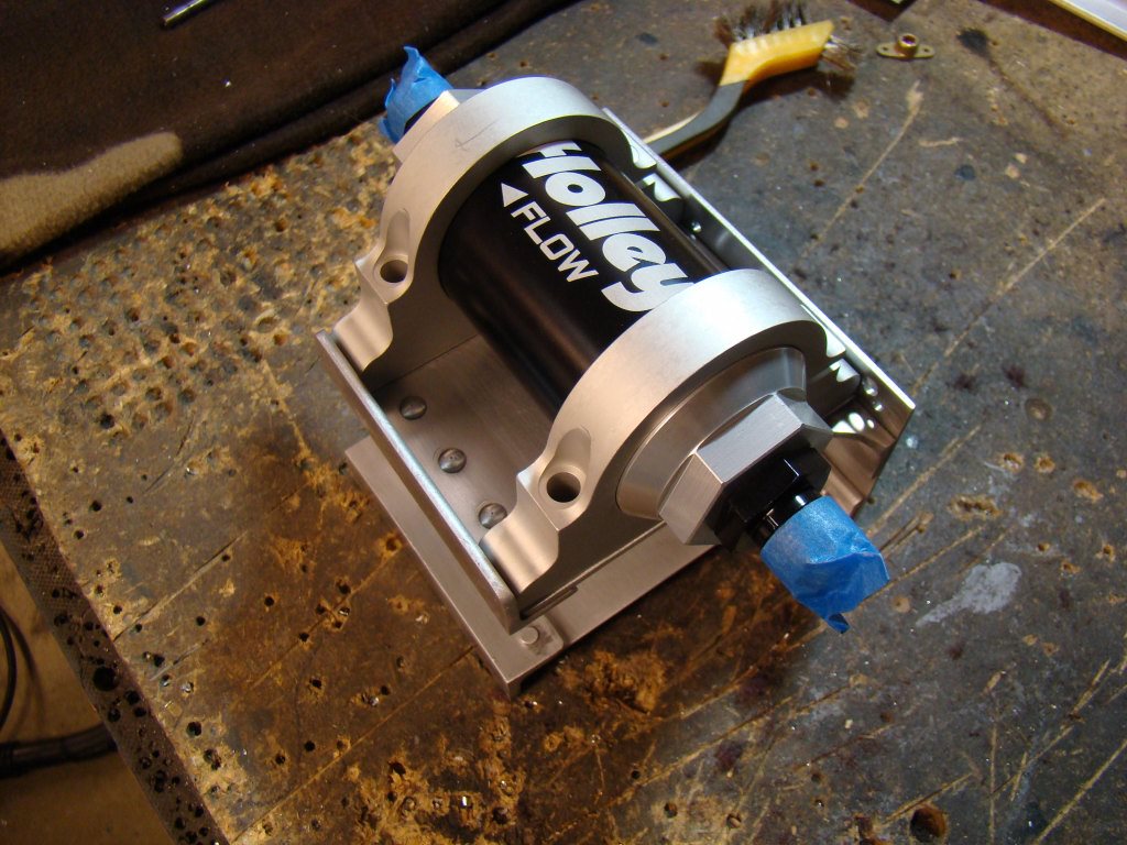
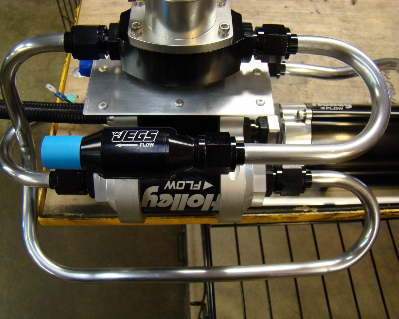
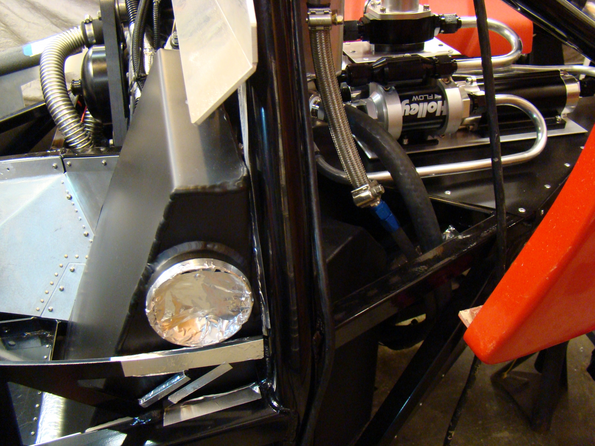
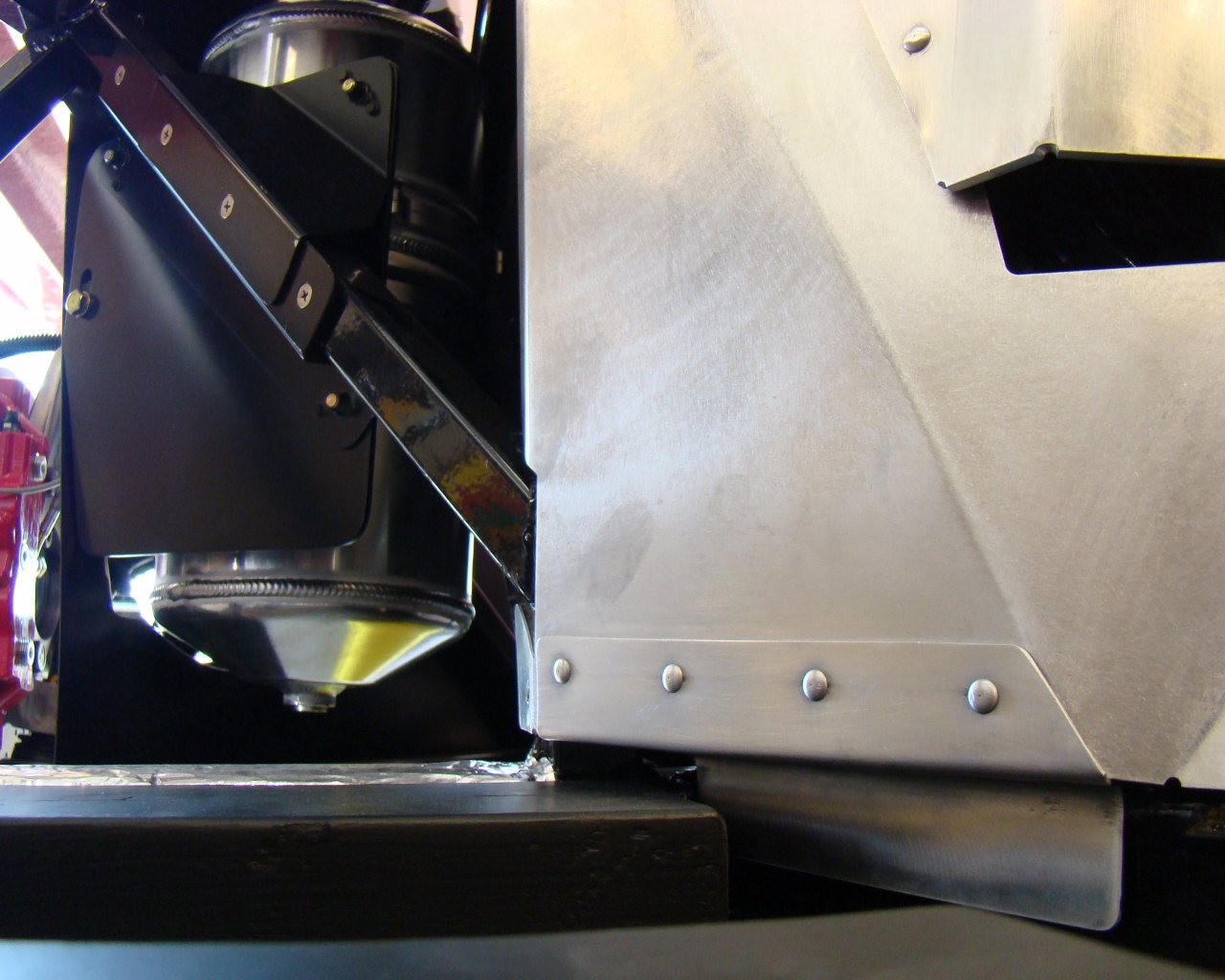
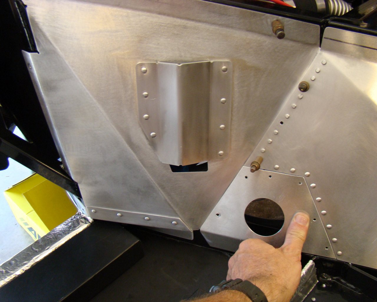
Components of the fuel system can be arranged in many ways. The below assembly was built as a removable unit with fuel feed and tank feed disconnect unions. It sits on the left side sheet metal platform just forward of the rear left wheel. It took considerable trial and fit to include re-mounting the Canton tank and building several hard aluminum fuel lines. After several iterations, I think I have something close that will work . The main question now is how the fresh air ducts will be routed for the intakes. Normally they feed through this area so I may modify this installation later. That was the purpose of making the assembly in this manner. It can be taken apart and re-assembled in a slightly different configuration later.
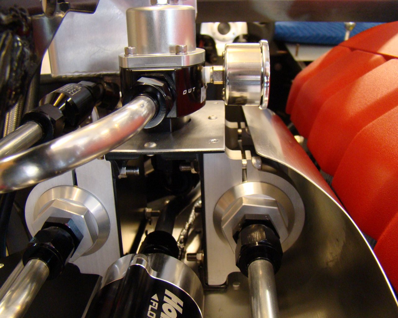
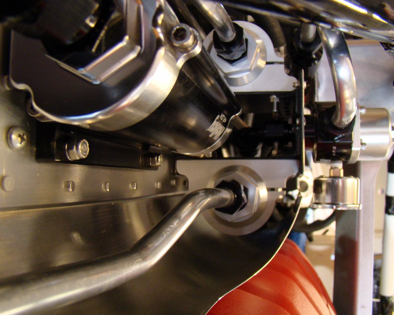
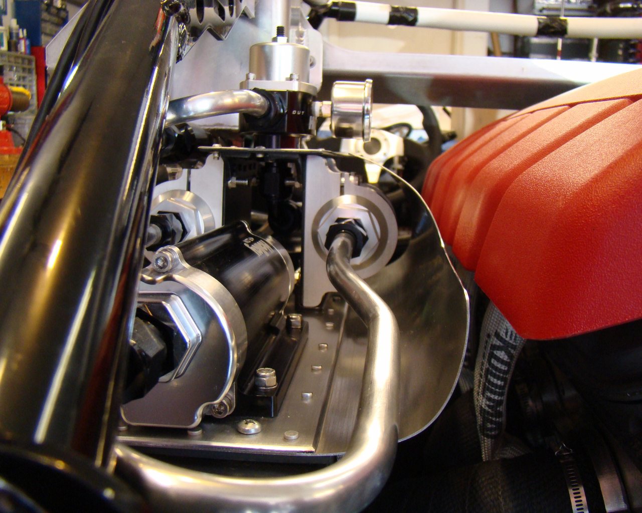
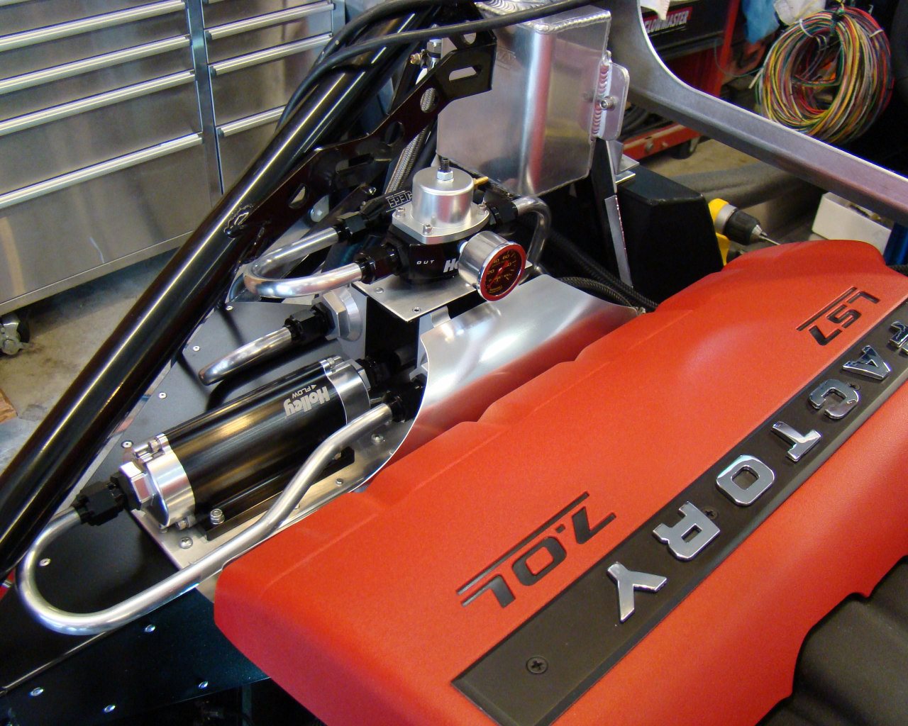
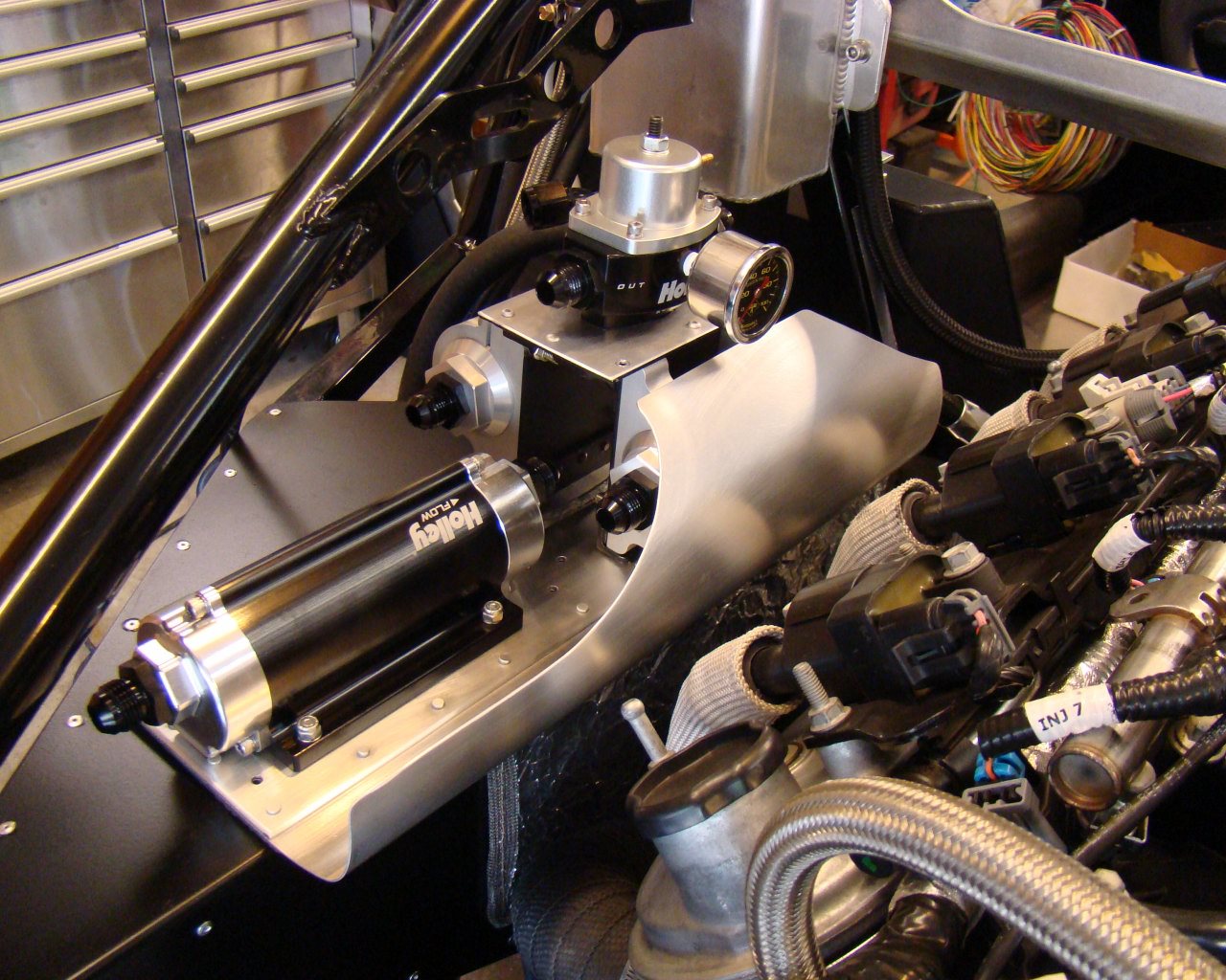
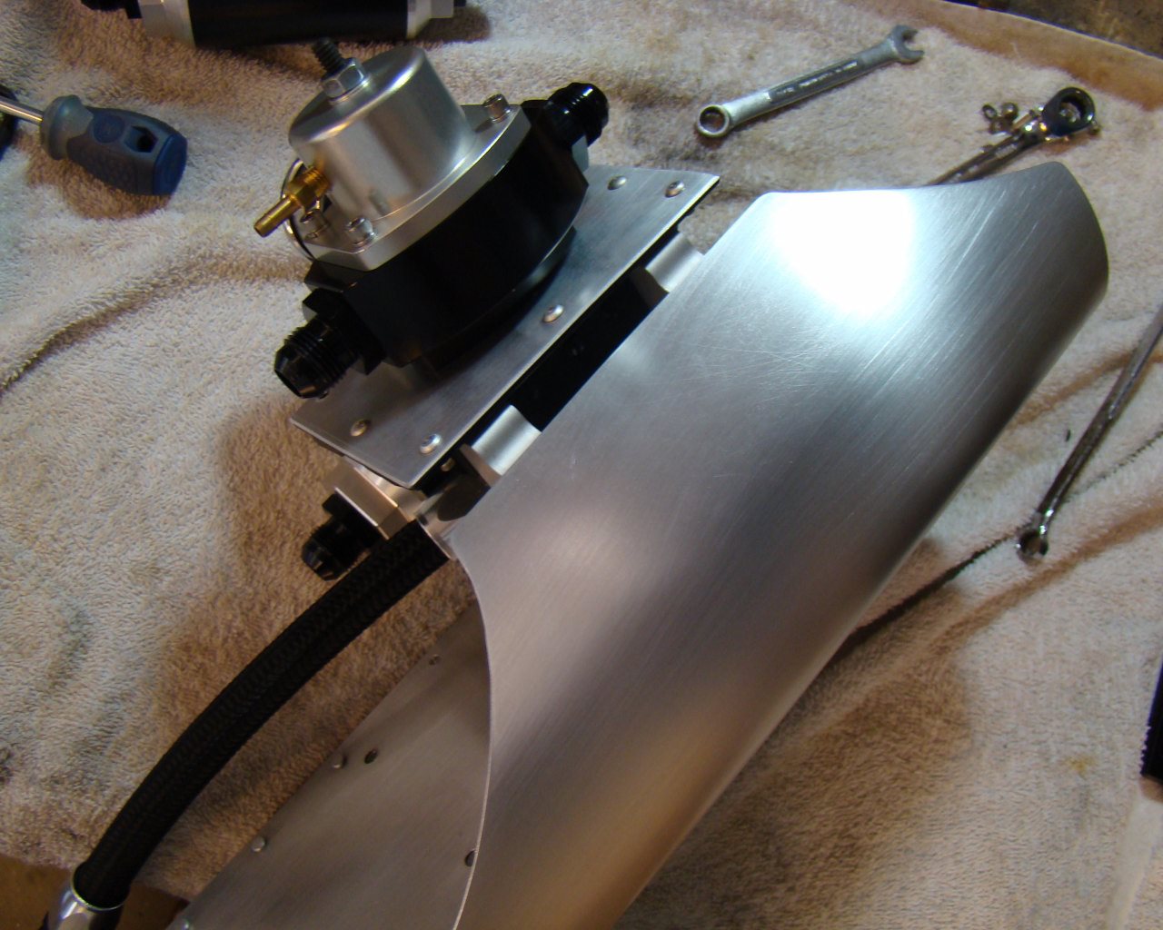
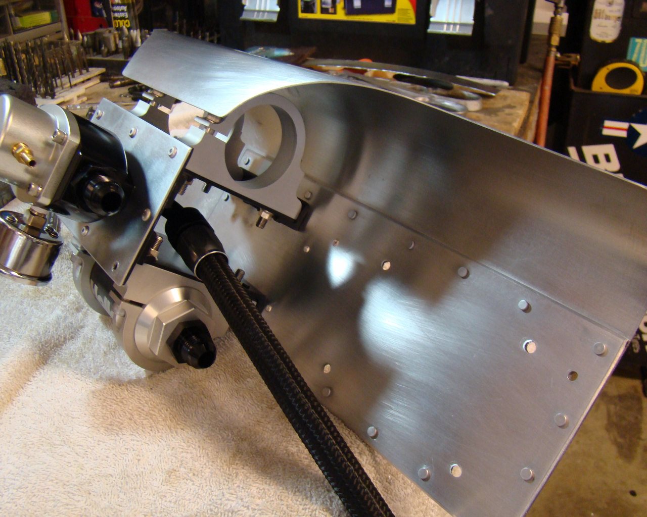
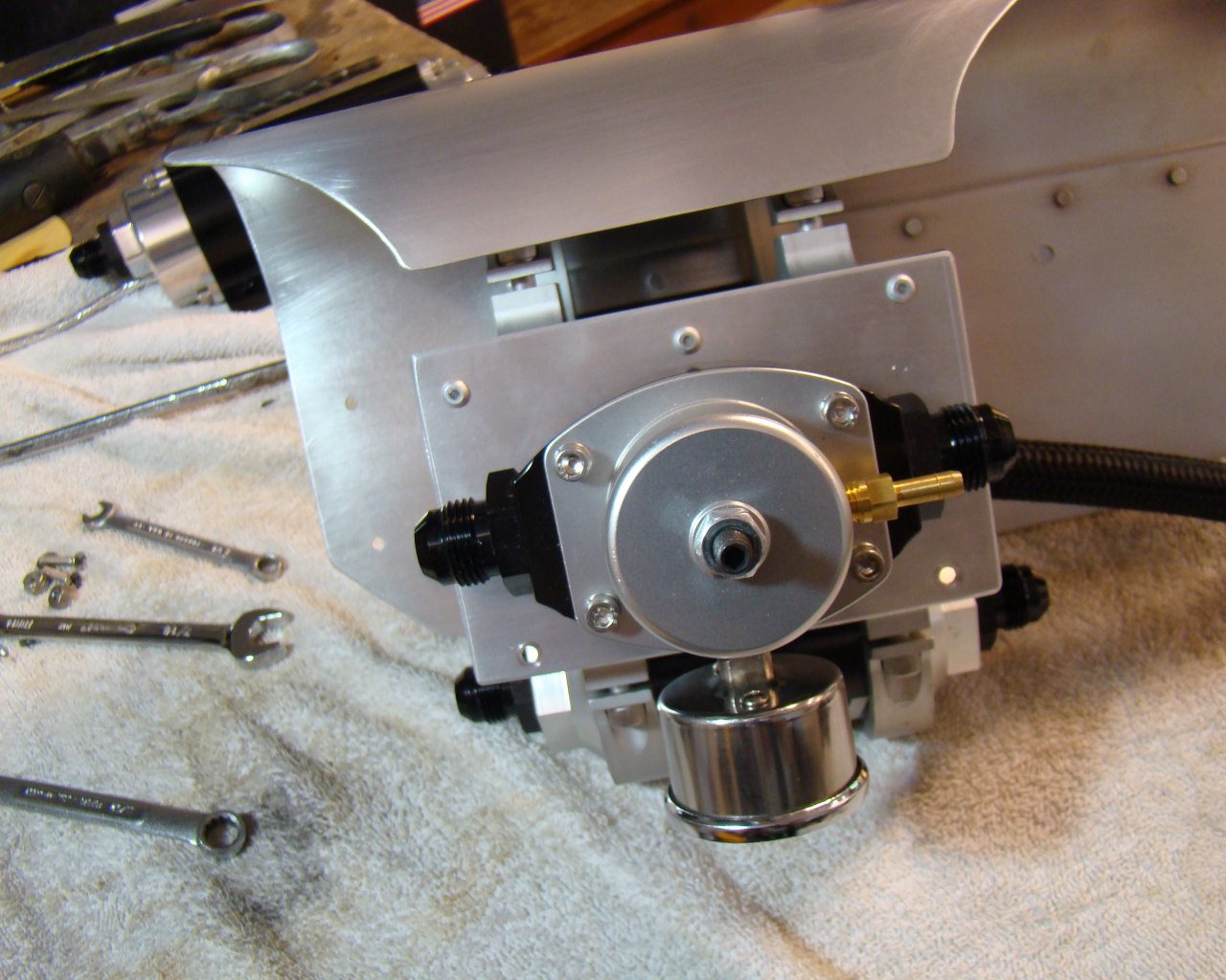
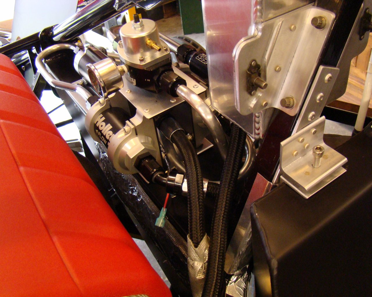
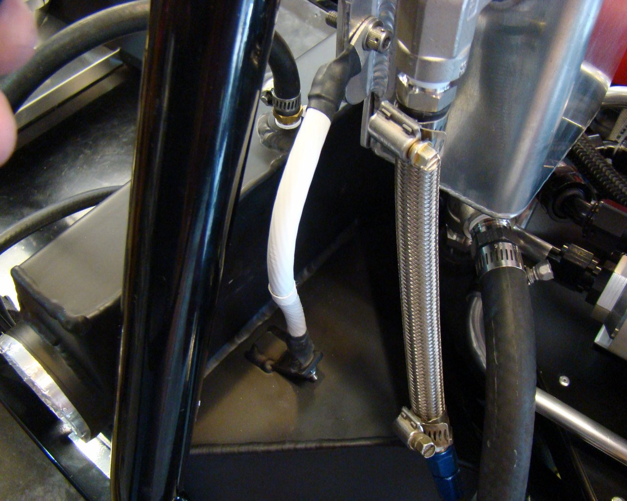
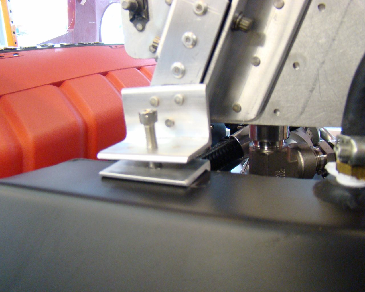
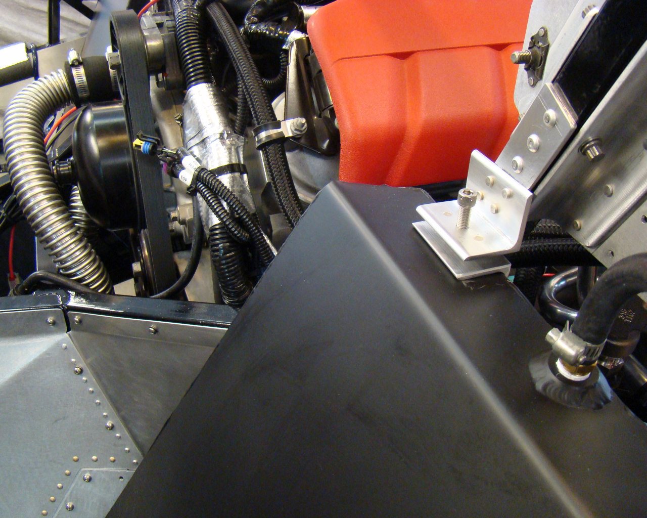
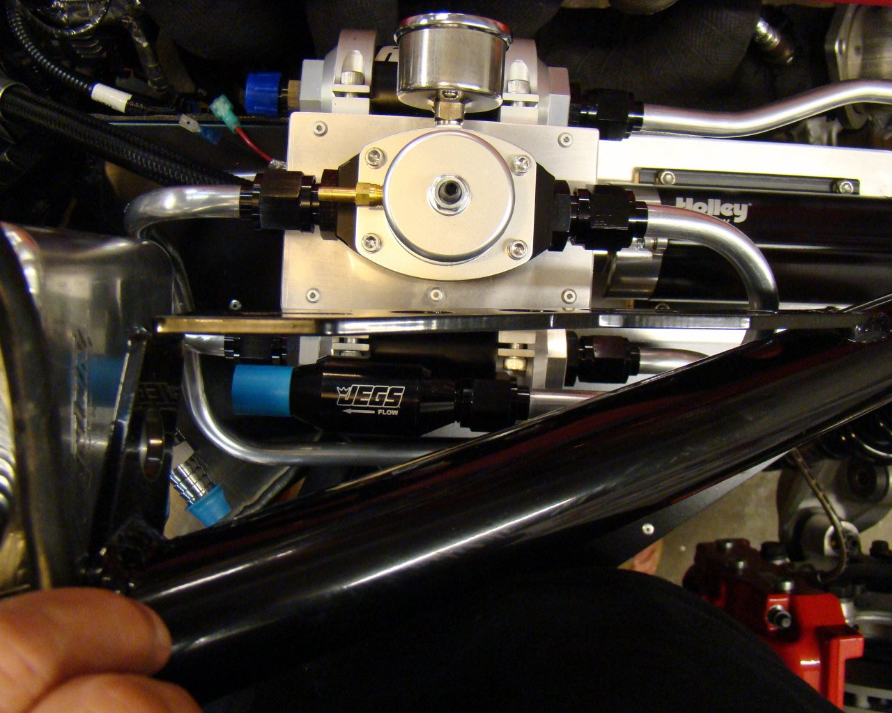
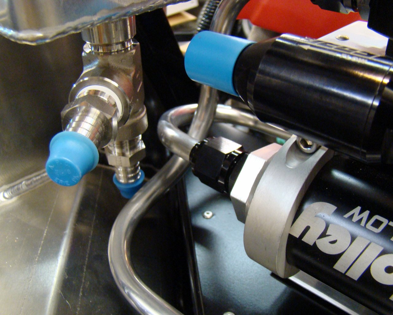
Here you can see the Jegs inline check valve for added assurance for quick starting. The check valve holds the fuel in the line at the fuel injector ports and prevents any backflow that might occur.
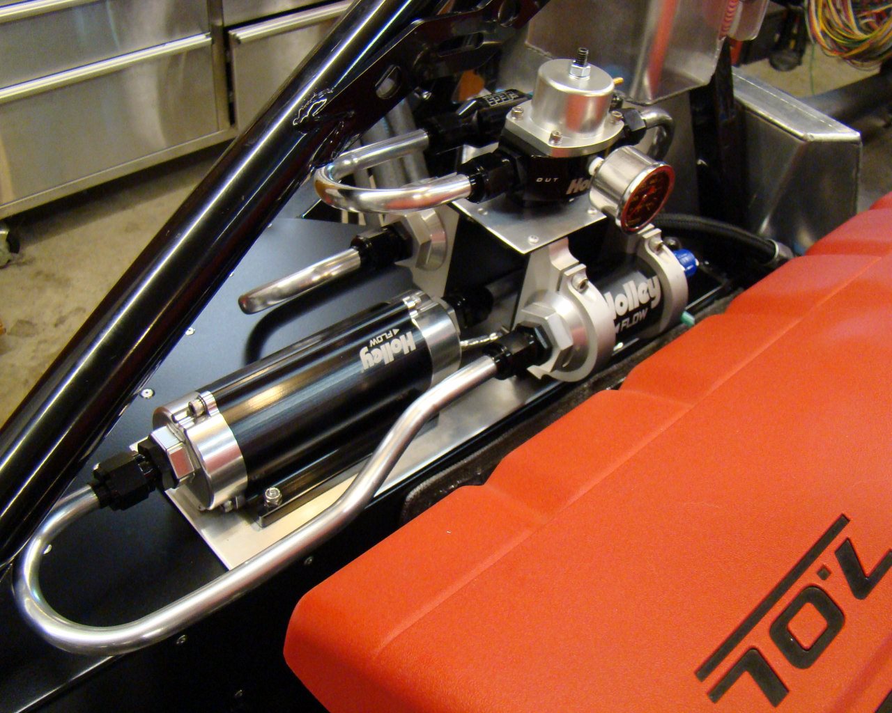
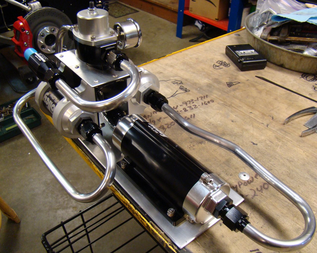

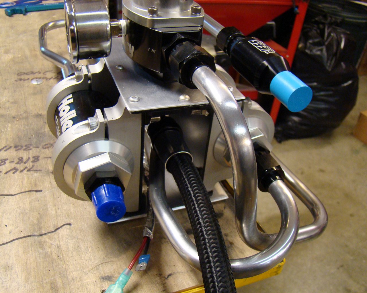
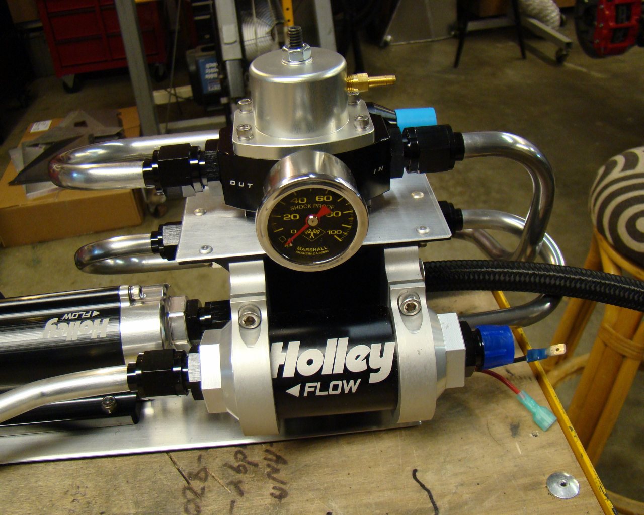
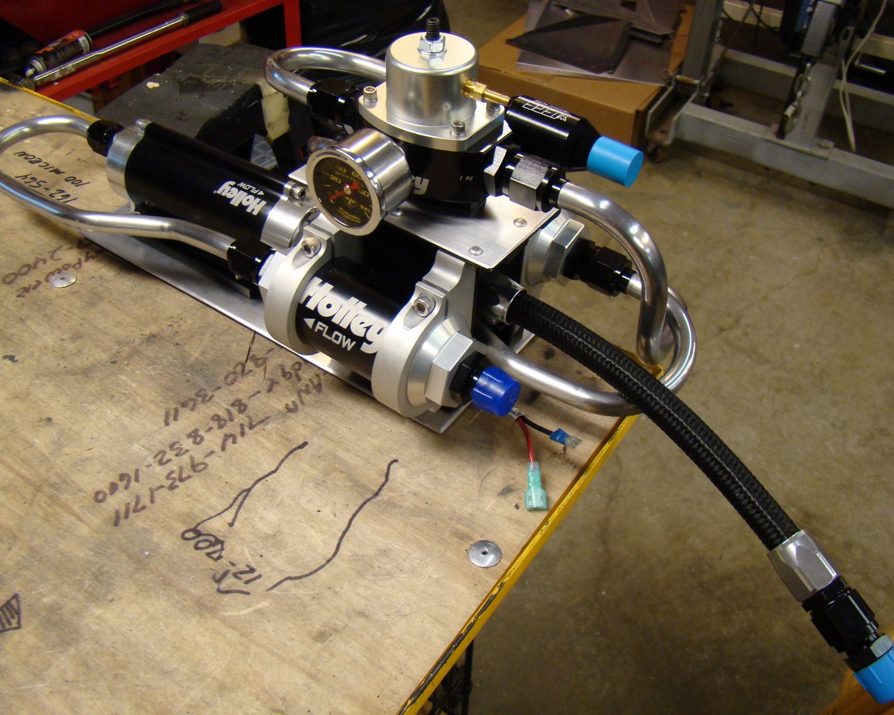
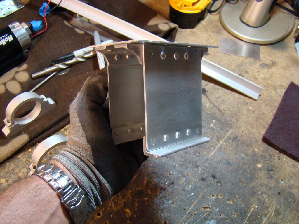
5/13/13 - I spent the last couple weeks off and on trying to figure out better ways to do the fuel system. I want an easy to maintain system that's tidy and that can be reconfigured easily. I've decided to go all-AN and purchased Russell Pro fuel line hose ends. Below you will see fabrication of the mount for the entire system. The idea is to keep everything tightly organized in a single unit and then mount the entire system on shock mounts. The lines between the pump, filters and regulator will be hard line AN 1/2" (-8AN). The feed to the engine will be Russell Pro nylon fuel line with a Jegs in line check valve to keep fuel at the engine for quick starts.
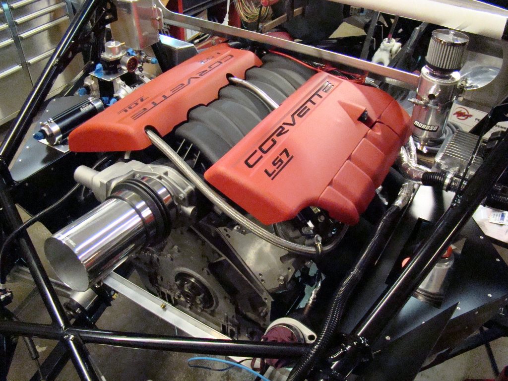
I'll leave the fuel system sitting there for now. Later when I get the tranny in and connect the exhaust and fresh air intake I'll drill holes for a permanent mount position.
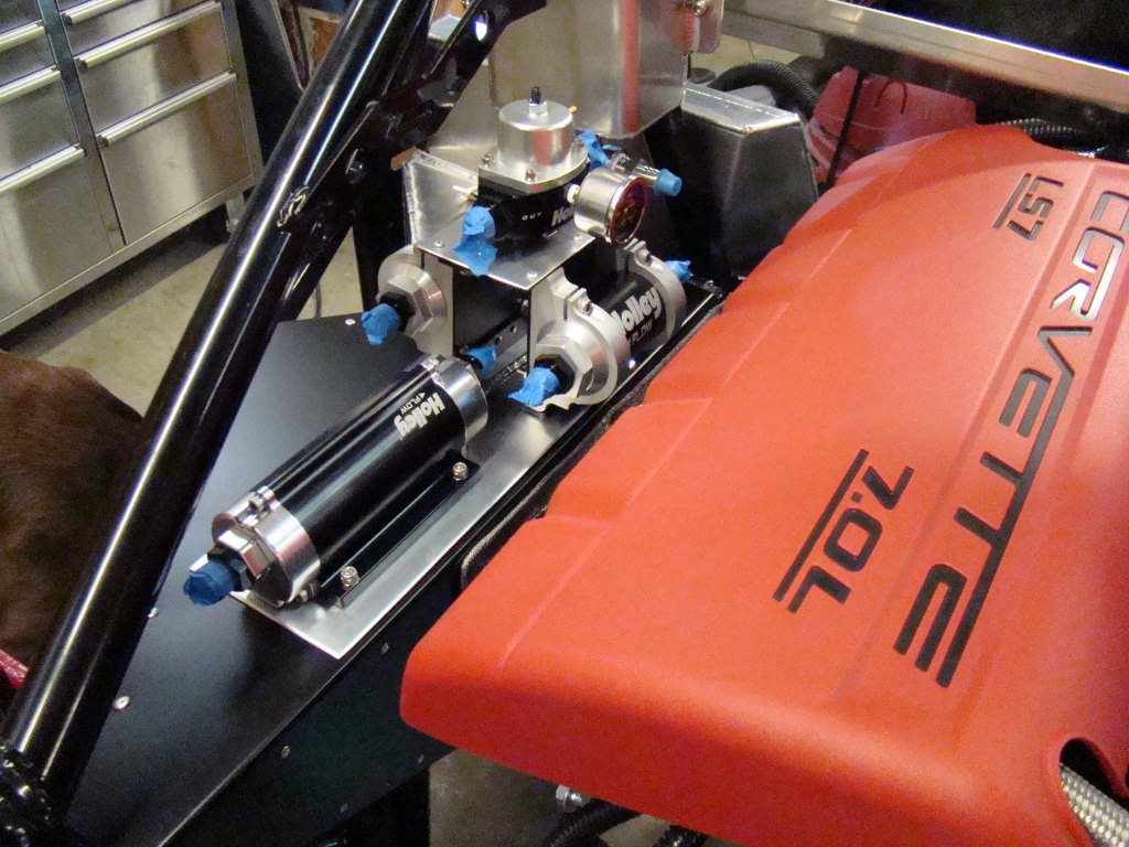
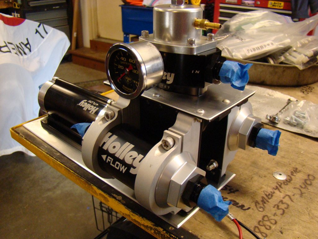
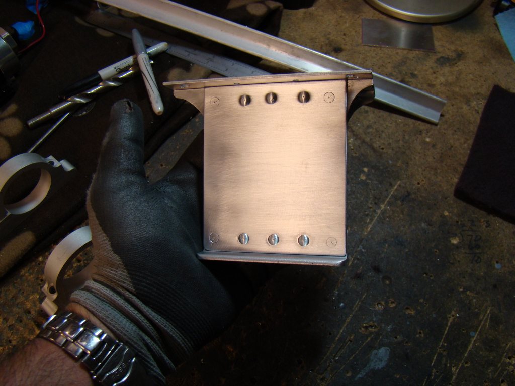
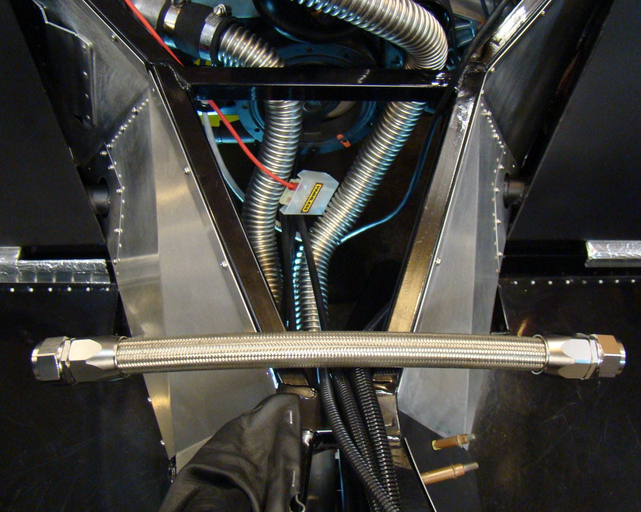
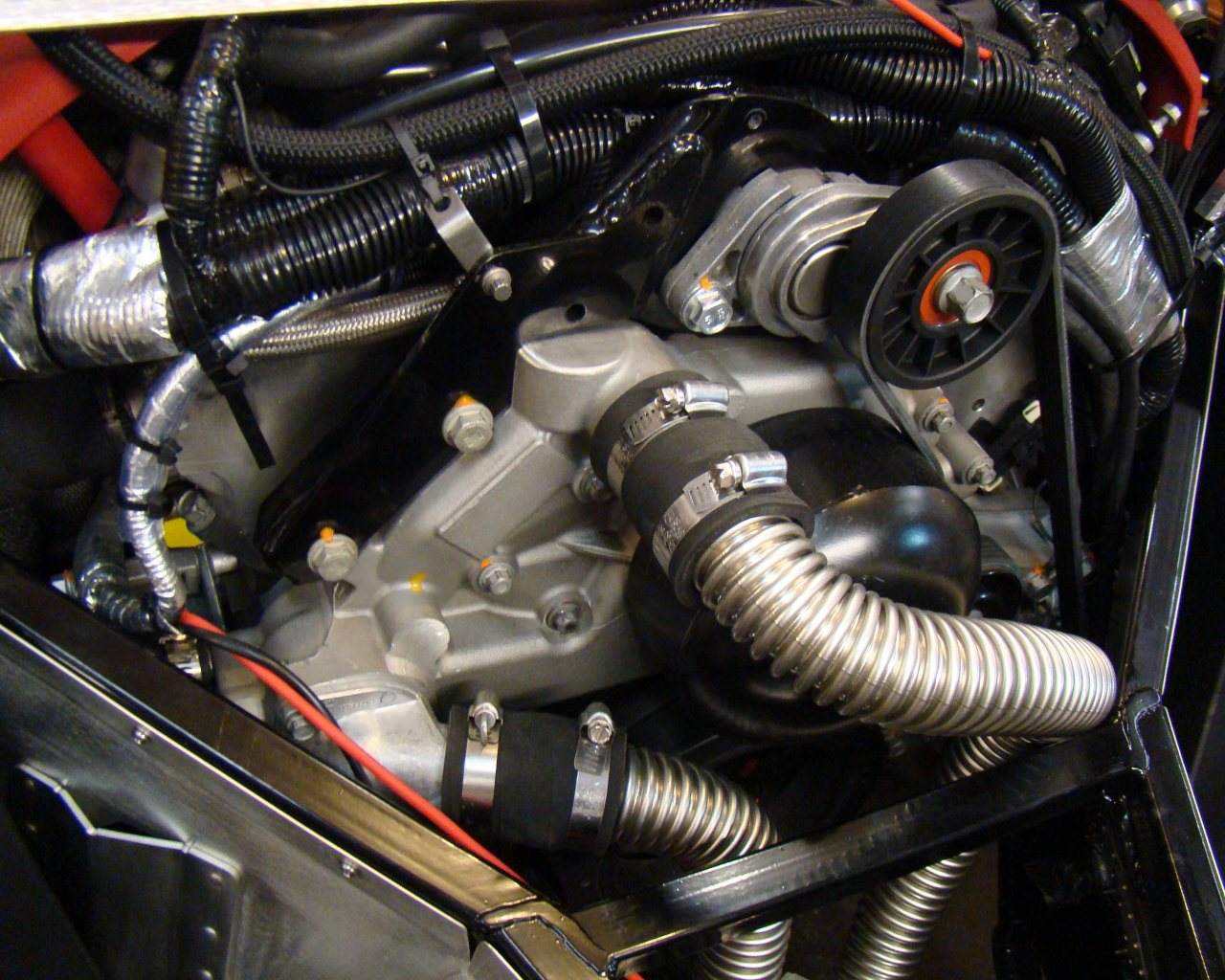
The system components are mounted to the lower base plate which is .080 aluminum. The screws are 10-32 Countersunk stainless steel coming up from the bottom to engage self locking nuts. This allows the entire unit to be mounted with 4 bolts or screws to the frame/sheet metal on the left side of the engine. I may use some kind of shock mount under the plate. I plan to use hard lines for plumbing the assembly in the picture to the left but will transition Russell pro nylon fuel line from the assembly, under the forward section of the engine and back up the other side. This will keep fuel lines away from the headers and over the top of the engine. We'll see how the routing works out. If it looks clean and safe, I may route along the forward upper engine near the firewall.
NEED TO VERIFY FRESH AIR INTAKE TUBES THAT ROUTE THROUGH THIS AREA!
It's too bad the ECM and main harness went to the right. The fuel entry point on the engine would have been a straight shot had all this been in the same place on the right side.
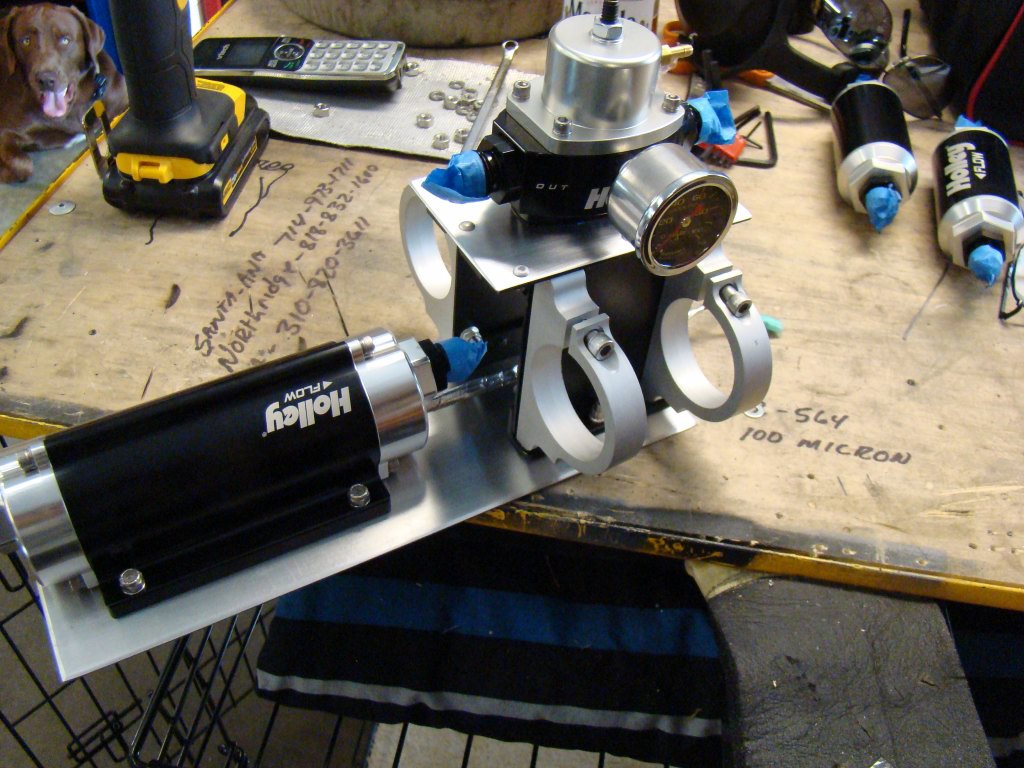
This is configuration #2 with the pump mounted to the side.
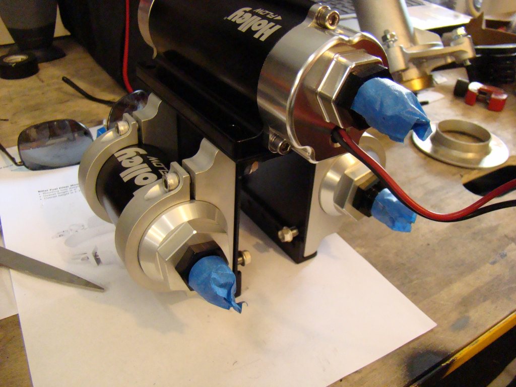
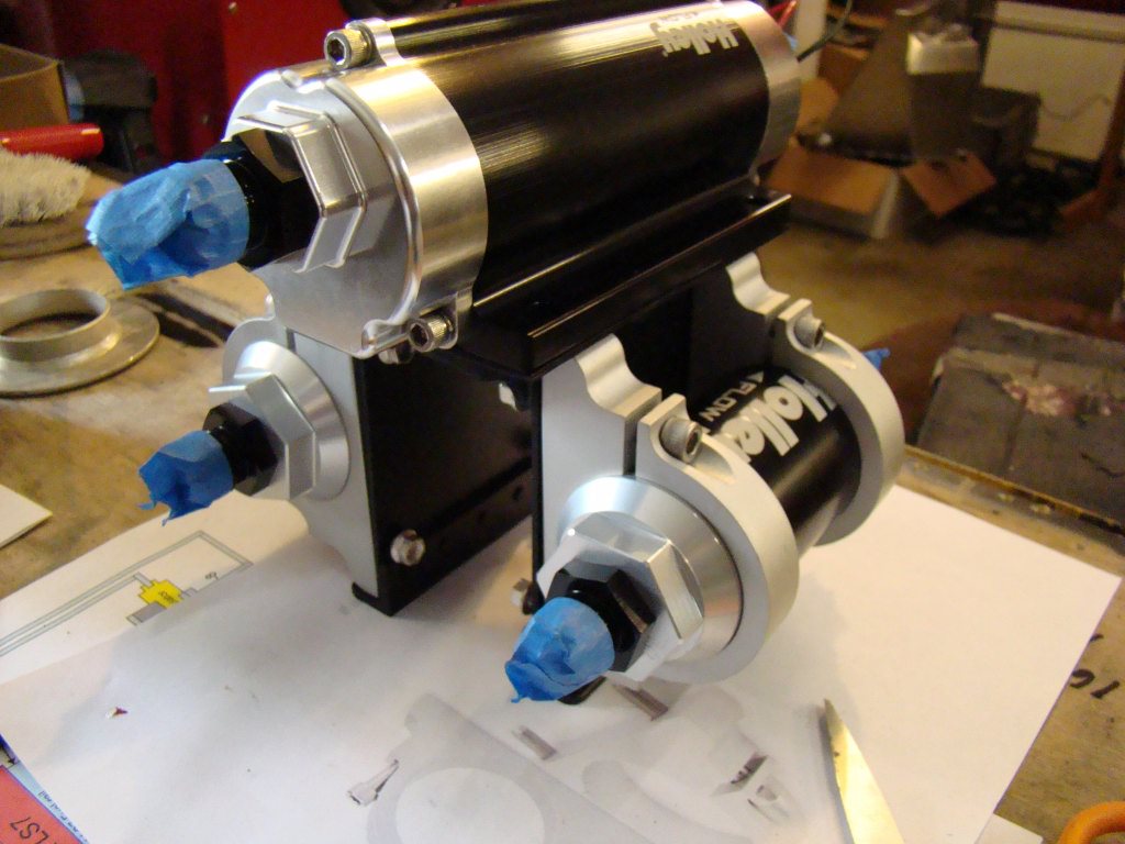
I started out with the pump on top but soon realized I'd have to mount the regulator there instead. The pump was long and the fresh air intake will interfere with the unit if the pump is mounted that high.
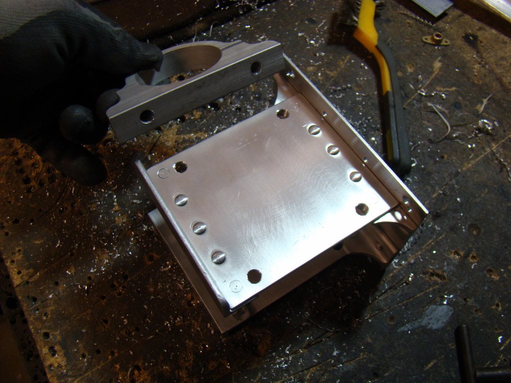
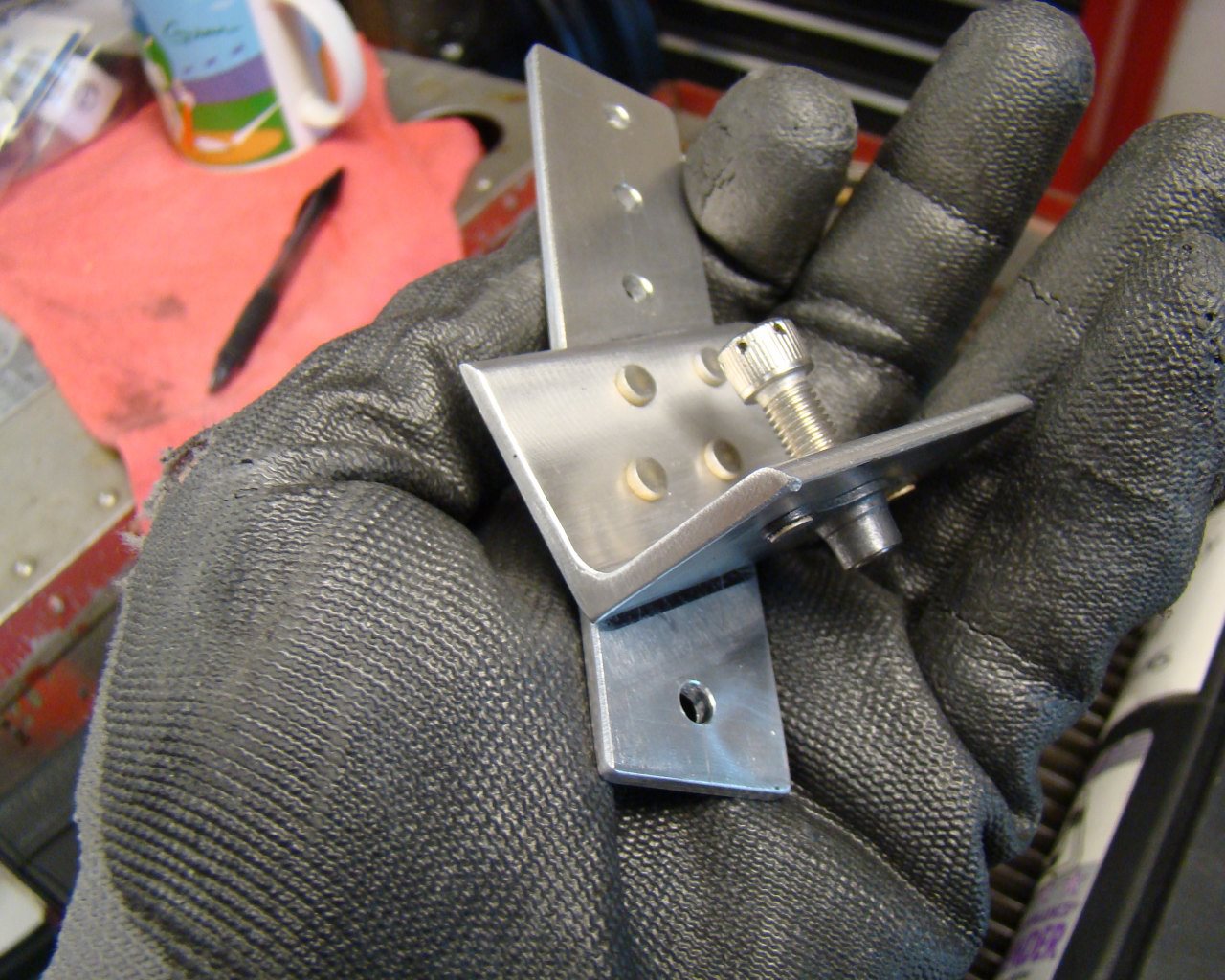
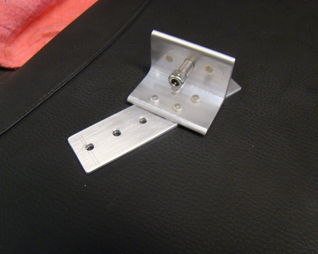
I had to reverse counterbore the 8 1/4" holes for the 2" filter clamps. The holes actually came out on the inside of the mount in the L-angle legs. Minor issue if you have a reverse counterbore.
