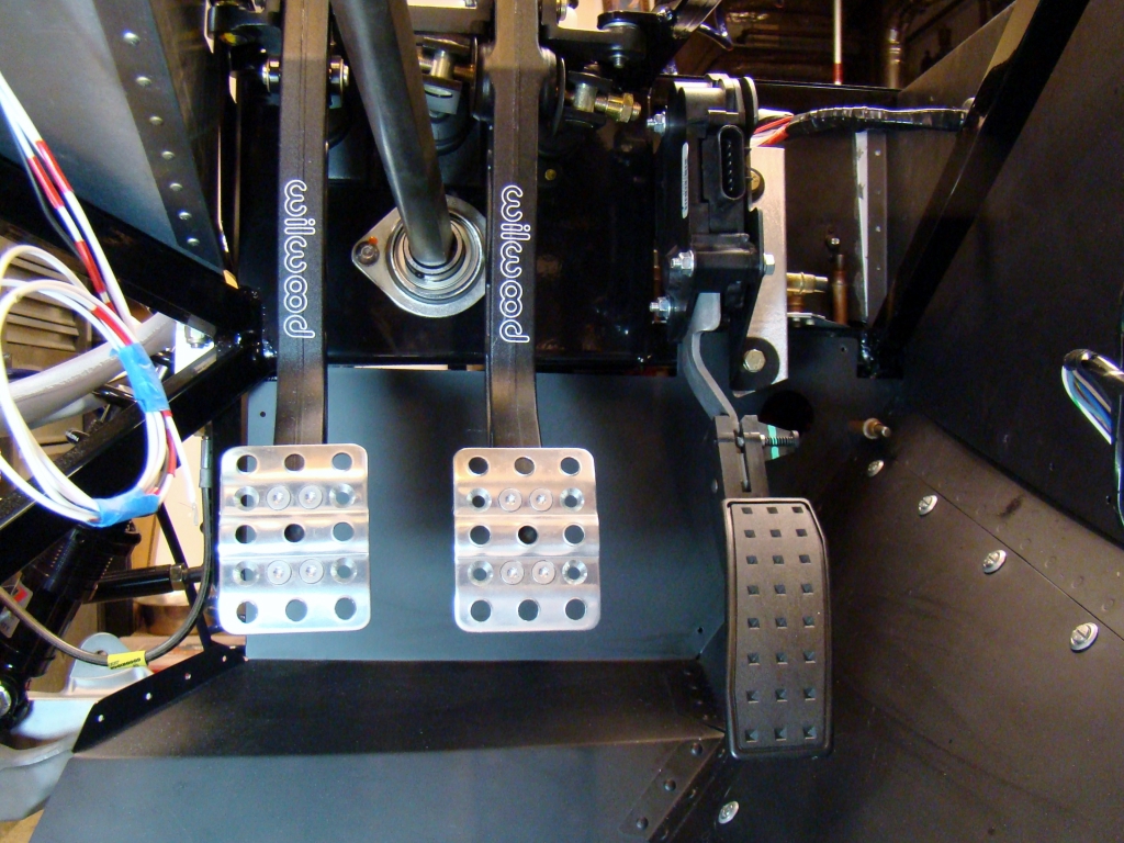
PEDALS AND SWITCHES
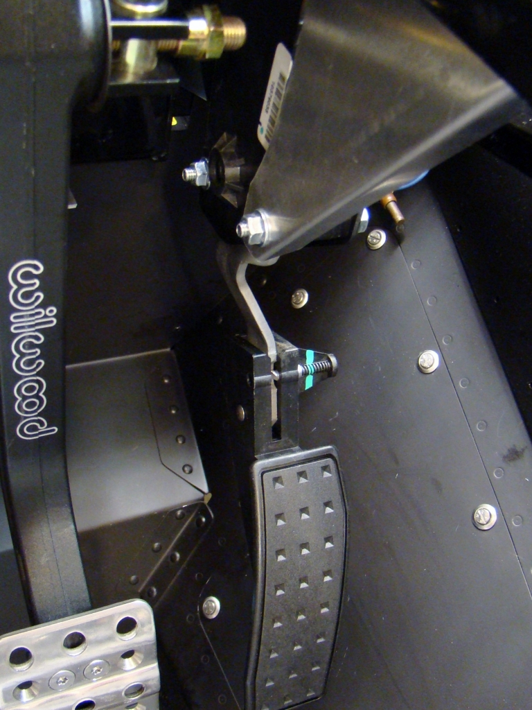
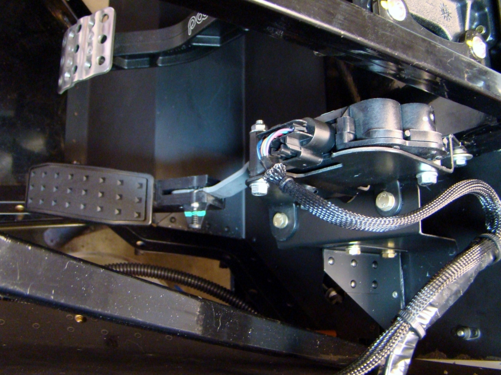
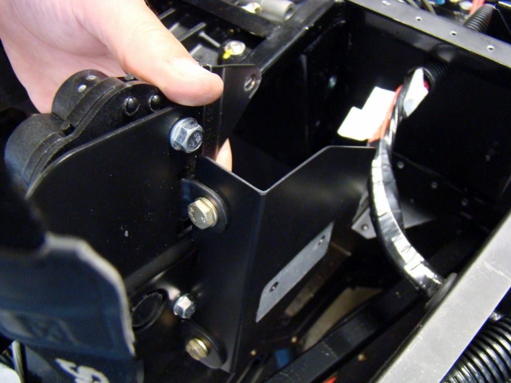
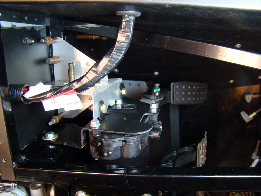
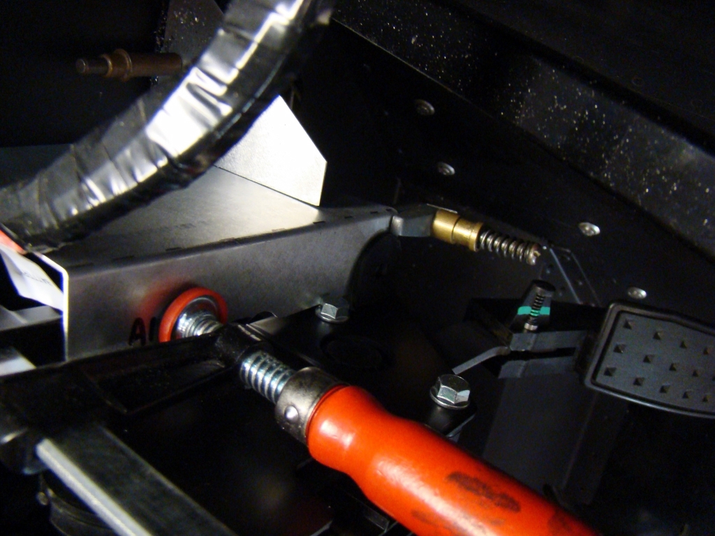
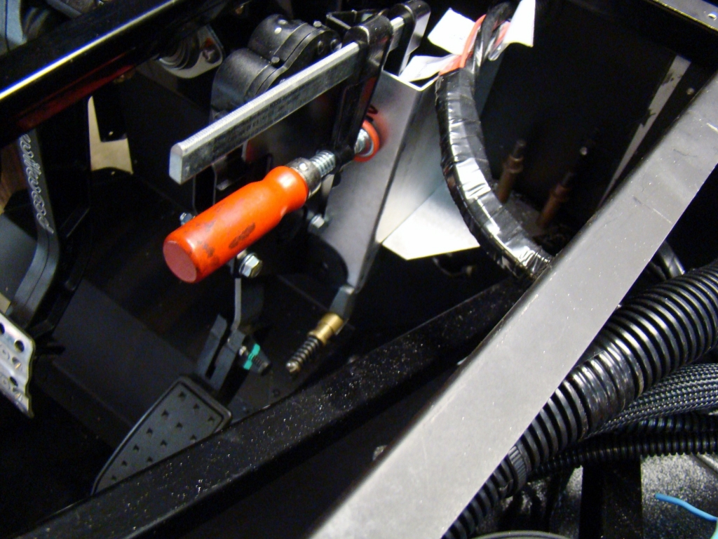
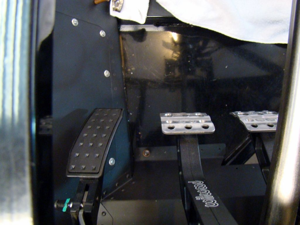
This configuration was meant to have simultaneous switch and stop engagement. The stop kept the pedal from bottoming out on the switch. I will remove the switch and trim the stop bracket to move about 1-1/2 inches forward. With the switch now located to the left and higher (riveted to the sheet metal side panel just below the 1" frame tube), only the stop will remain here. It will still provide the same function.
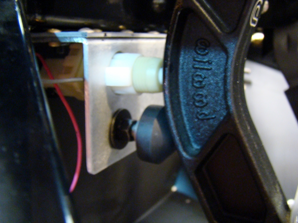
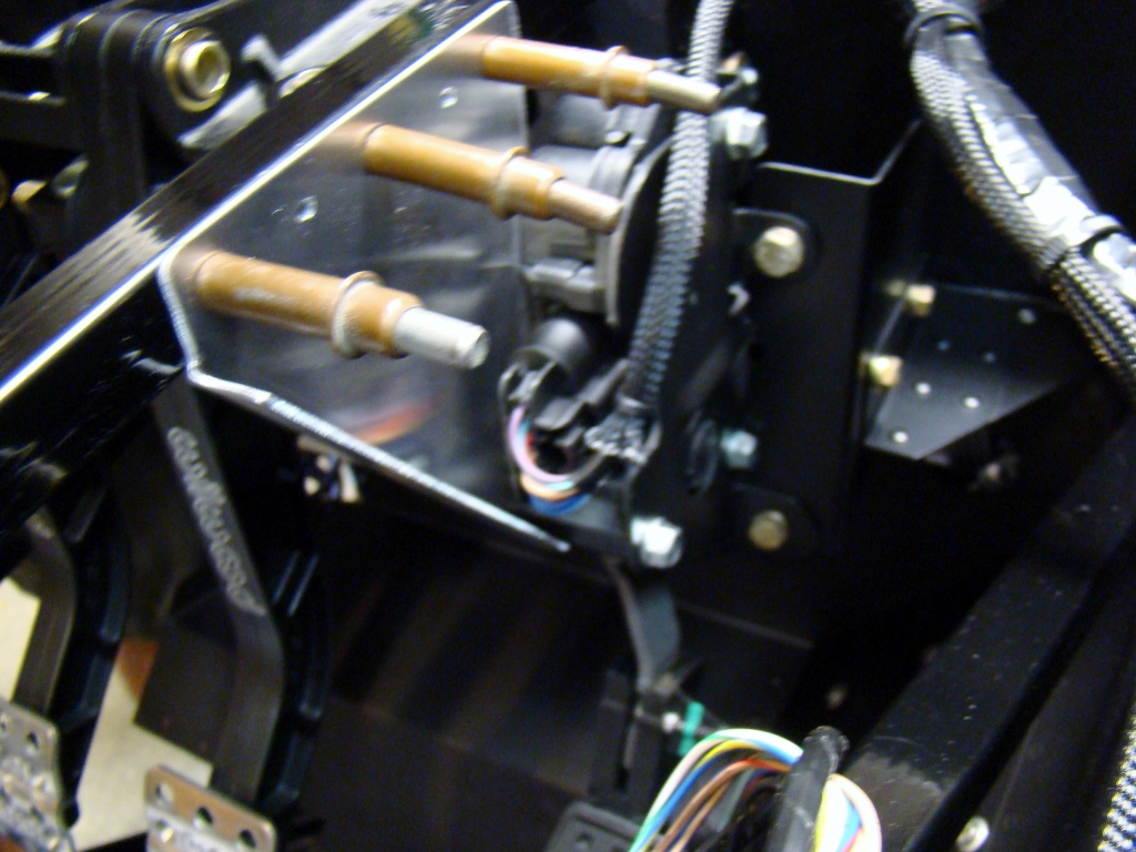
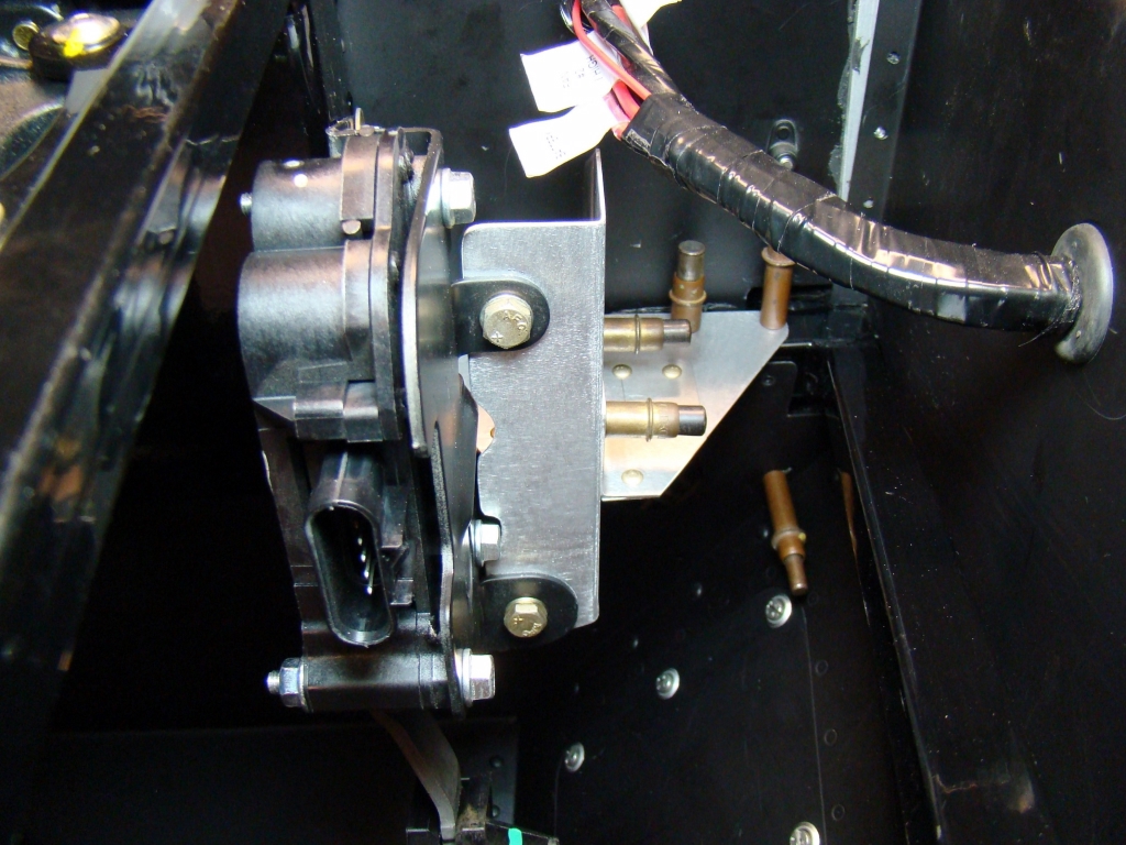
For the ISIS system and Racelogic traction control, a clutch safety switch is needed. Additionally, a stop is needed for the clutch pedal as recommended by the folks at Medeola. This was my first configuration. Although it worked and was relatively stiff, the switch body ended up being too long and butted up against the firewall under the master cylinders. I will add photos of the new configuration which uses an L-Angle switch bracket riveted to the sheet metal just forward of the fuse box on the left side of the car. I drilled a 5/32 hole in the pedal web and used a 2" screw with a plastic stop for switch engagement. This is on the upper portion of the pedal. To remove, it will be necessary to drill the rivets out from outside the car.
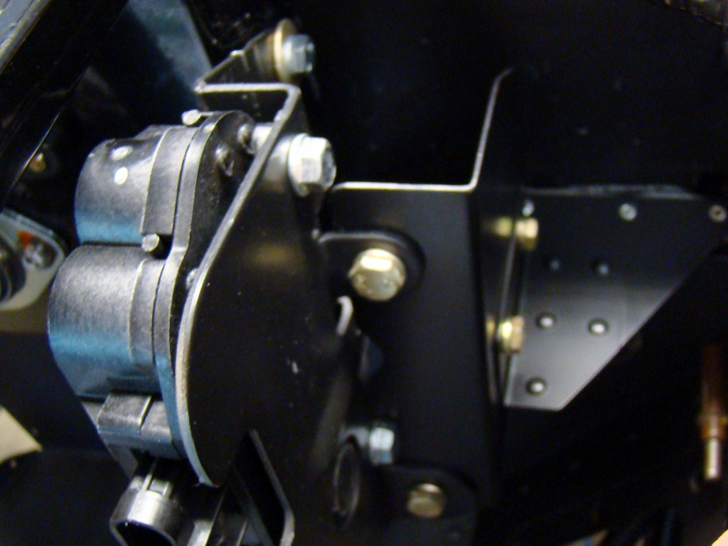
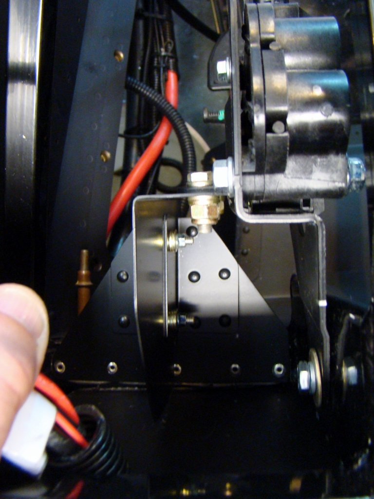
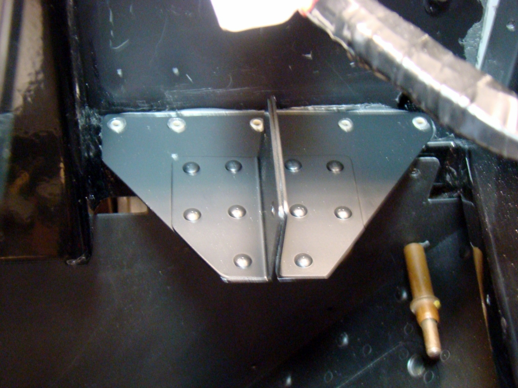
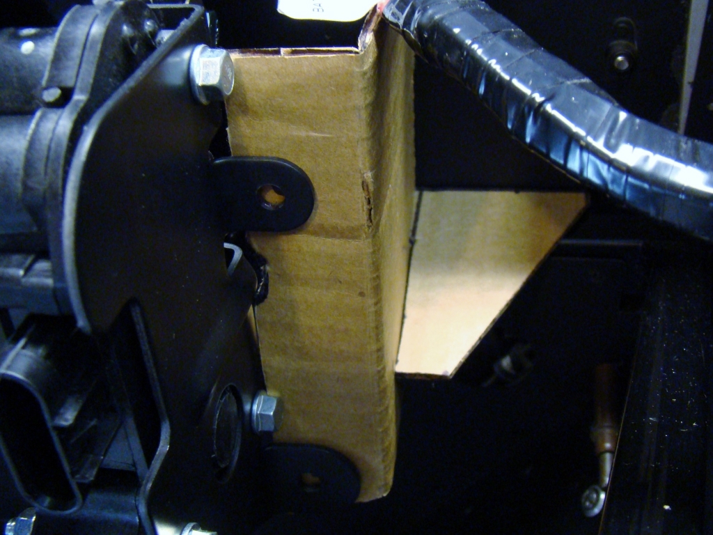
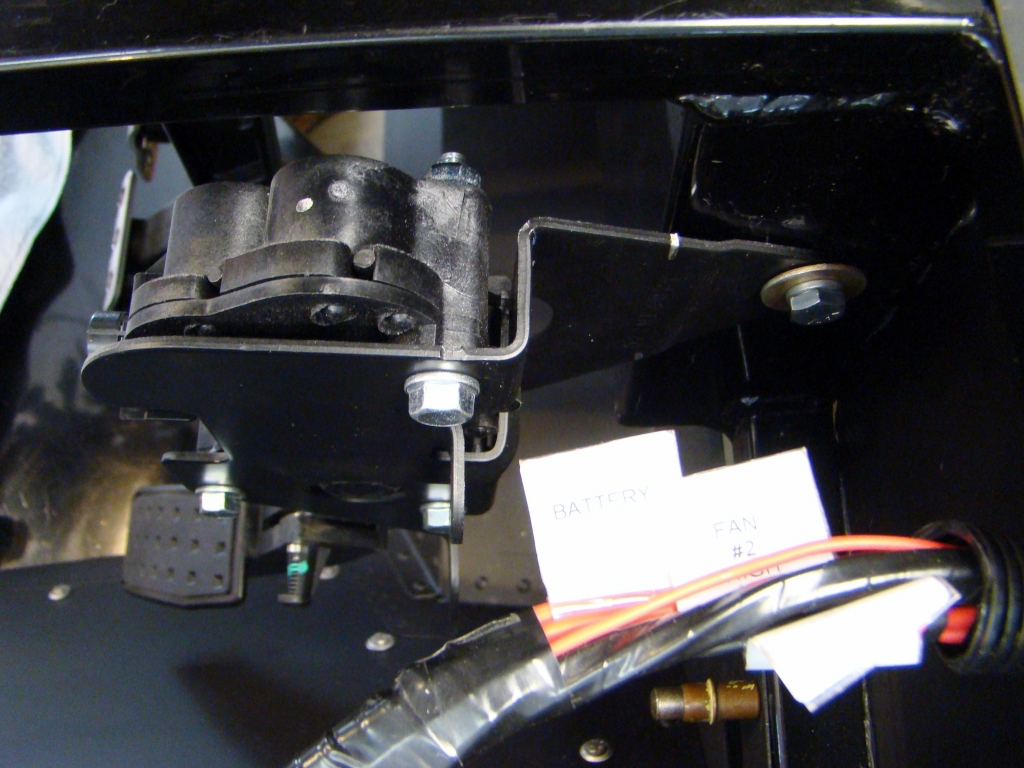
To reinforce the pedal in the vertical axis, a triangular angle plate is used. It engages the lower pedal assembly frame bolt that passes through the pedal body. There are three of these bolts. Only one is used to secure the pedal to the angle. The upper part of the angle is riveted to the frame.
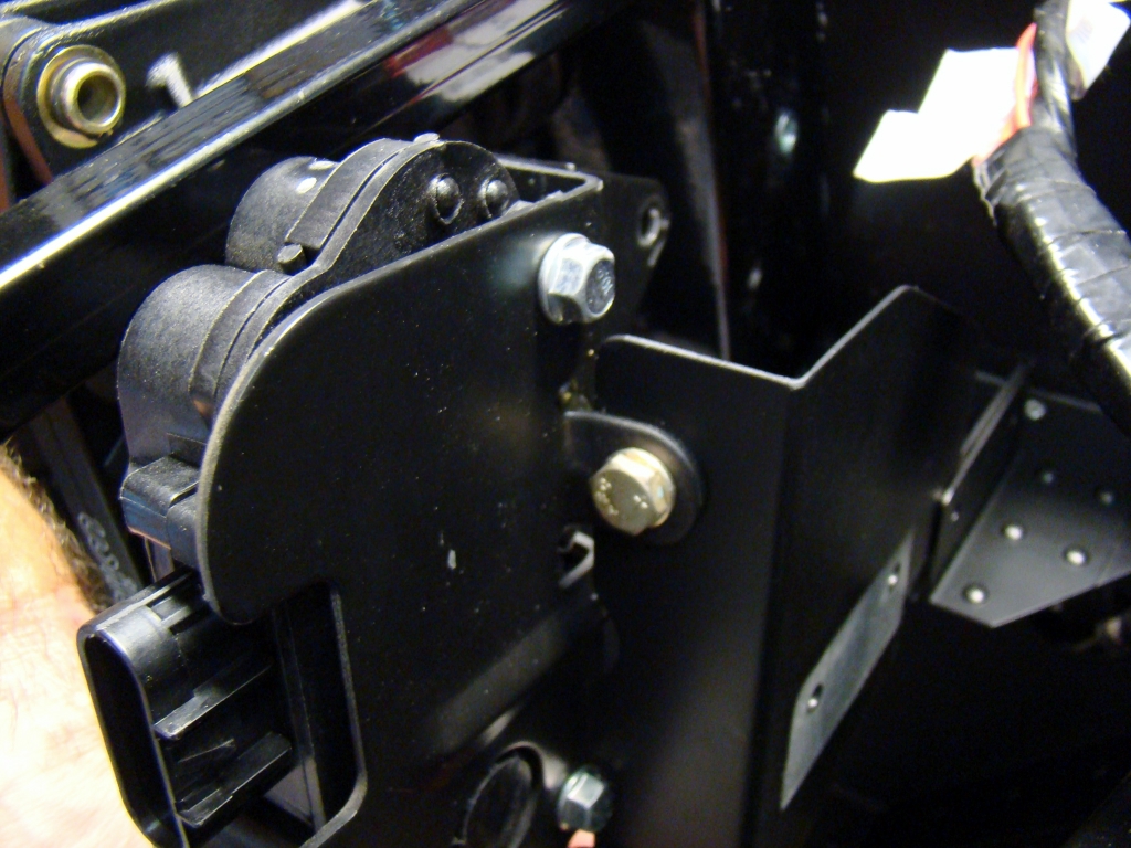
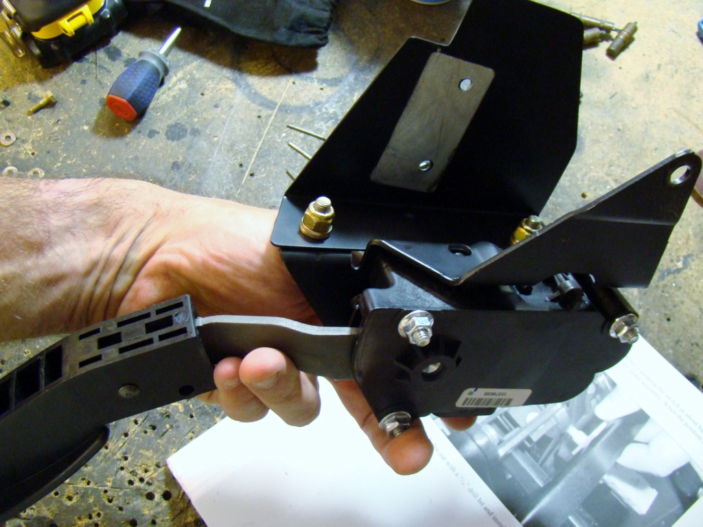
This shows how the pedal is removed for maintenance
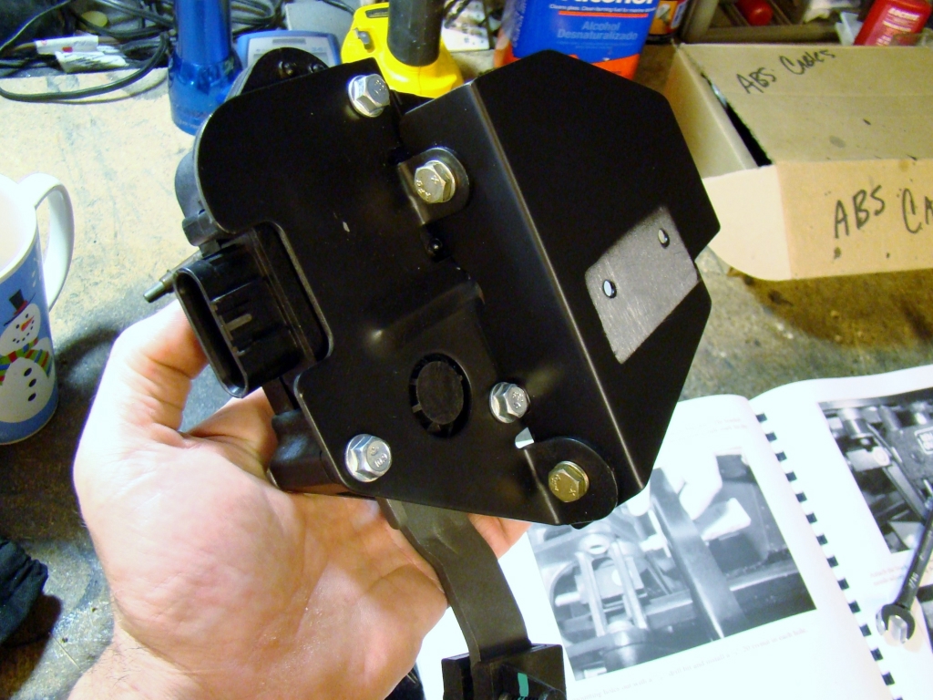


After fitting all the pieces and drilling the mount holes, the pieces are removed and painted.
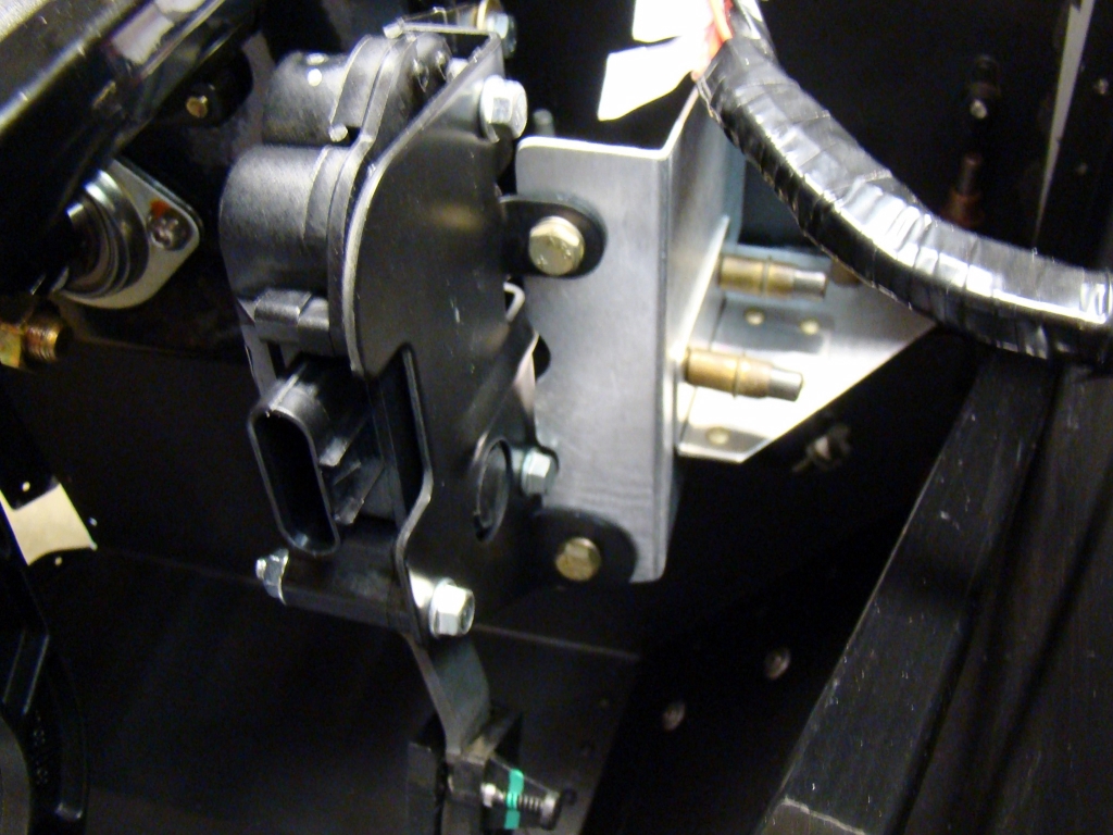

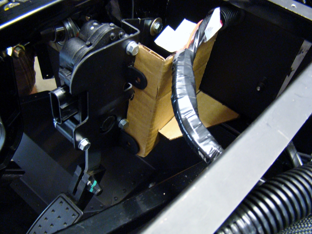
The angled plate that engages the fore/aft support bracket is used in conjunction with two bolts to attach the pedal bracket to the L angled plate.
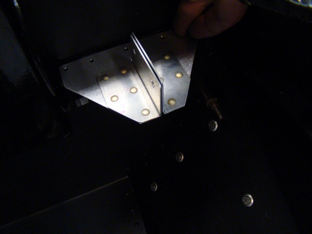
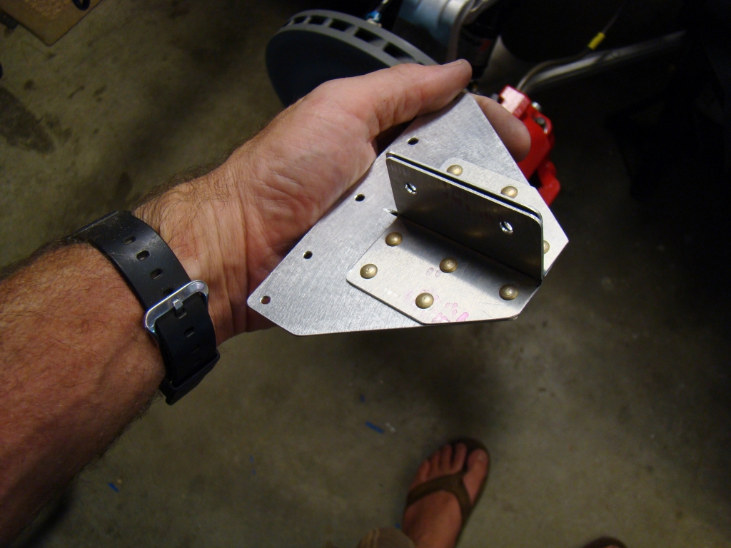
This assembly is riveted to the top of the 1" square frame tube forward of the pedals. The dual L angles are drilled so that the pedal assembly can be slid between the brackets. Once in position, bolts are used to secure the pedal in it's fore/aft position.
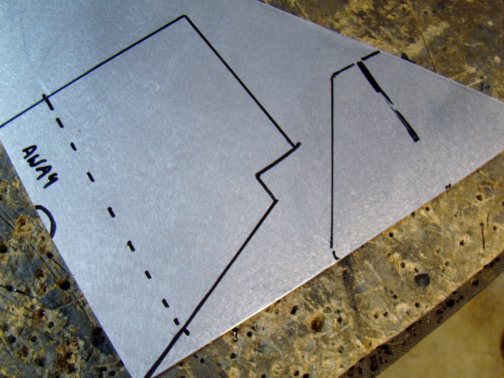
The sheet metal patterns were cut and bent using the cardboard as a reference. This saved time and metal. The pieces were bent on a sheet metal brake.
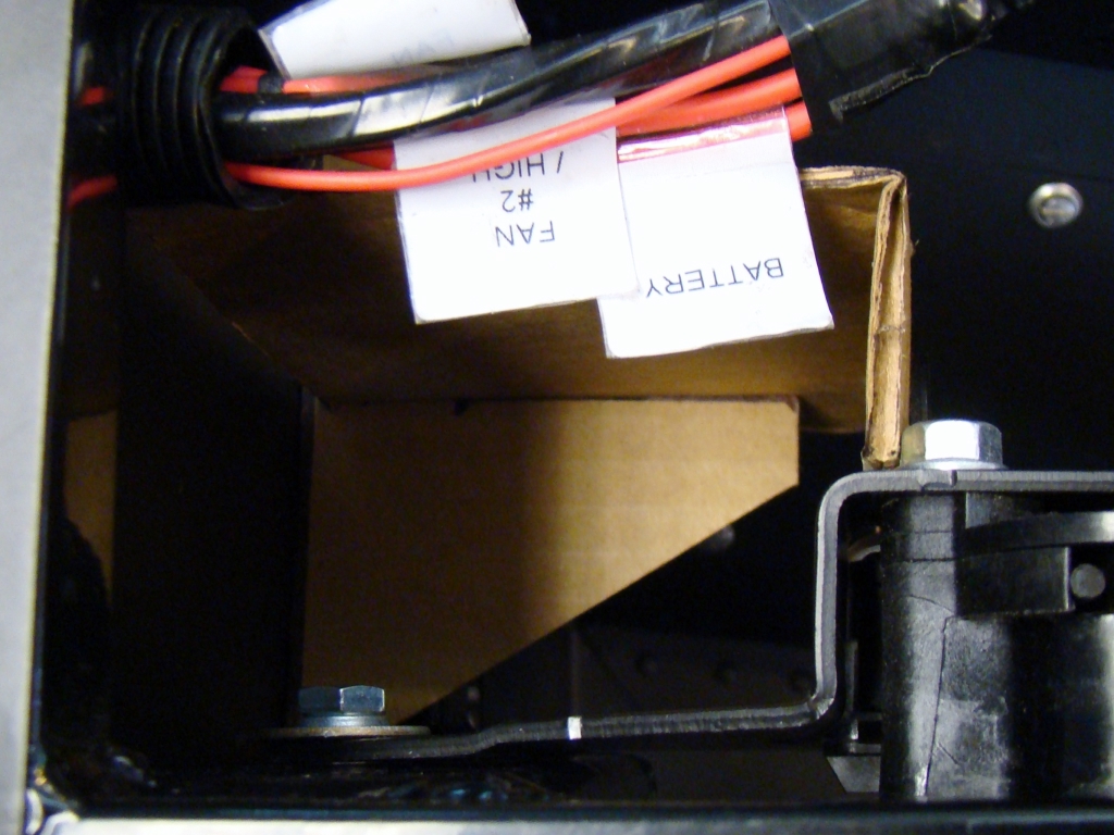
Cardboard mockup brackets being fitted
With the pedal in position, I made templates. Although out of sequence in the photos, these patterns were made by tracing cardboard templates that were fabricated as mockups for trial fitting.
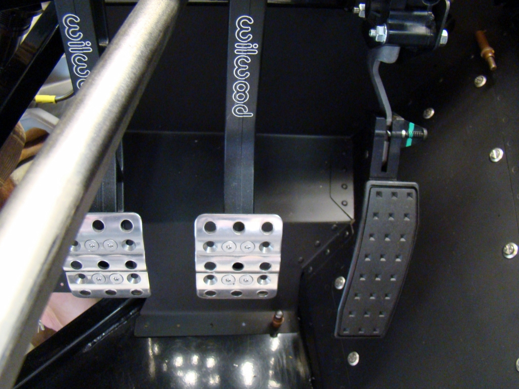
Basic position after measurements
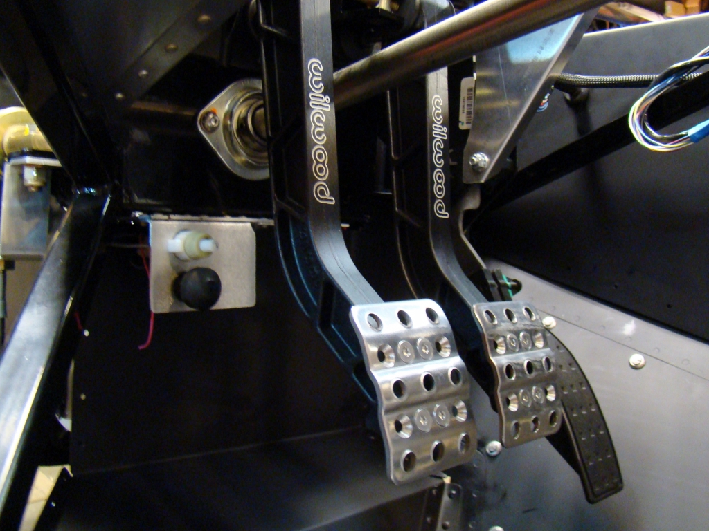
The bent pedal bracket was performed in a metal brake. The stand alone harness came with the pedal and bracket without the bend. This bent tab spaces the pedal correctly and keeps it in a position that allows for build up of the support brackets that will take up for and aft loads and vertical loads.
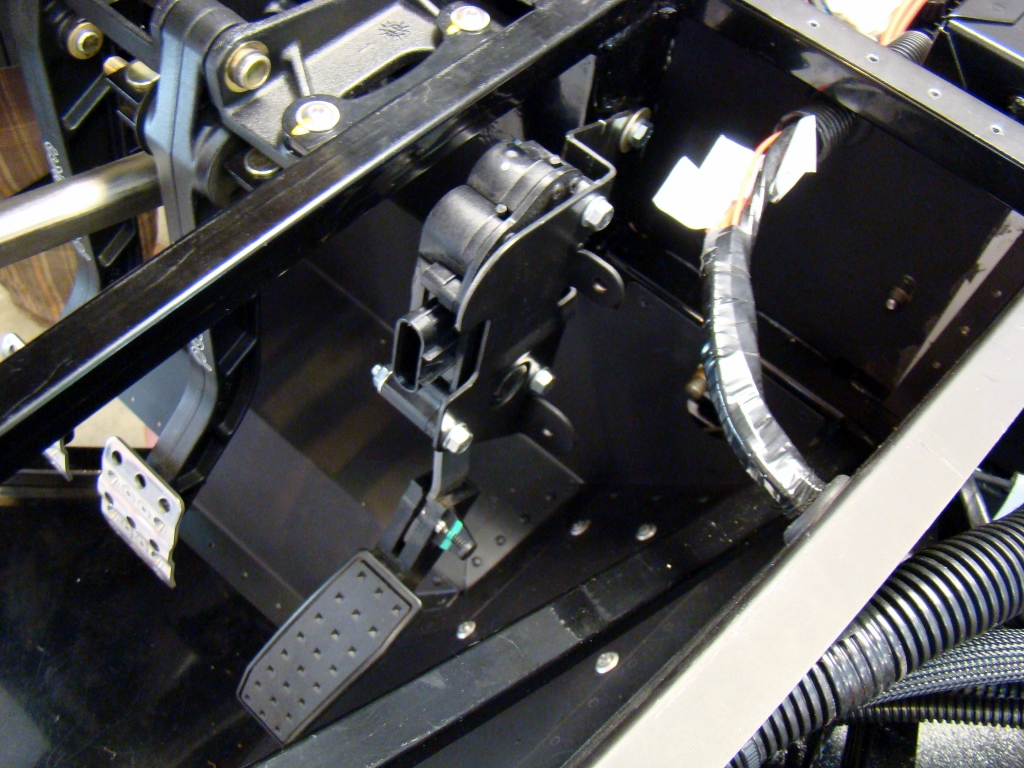
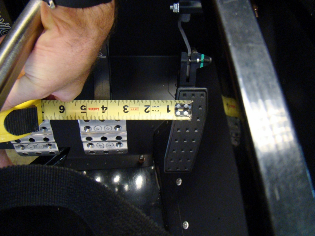
The stand alone harness Fly-By-Wire pedal is shown in the basic position. The forward most attach point with the bolt head shown in the photo was bent 90 degrees to align with the side of the steel frame box that the Master Cylinders are mounted to. The pedal centerline was located 4.5 inches from the centerline of the brake pedal based on a 2012 Grand Sport Corvette pedal arrangement.