COOLING
As usual, the upper pictures are the most current. As you scroll down, you will see all prior work in this category. Use the site map below to go directly to other pages.
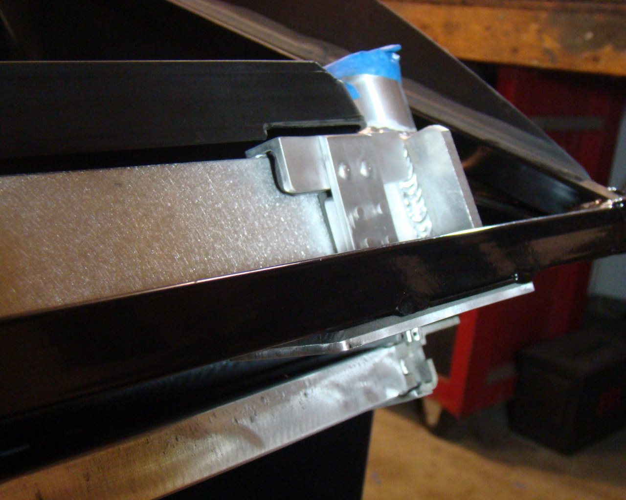
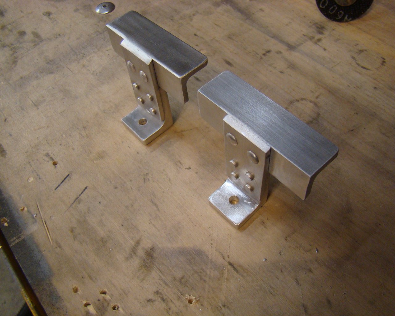
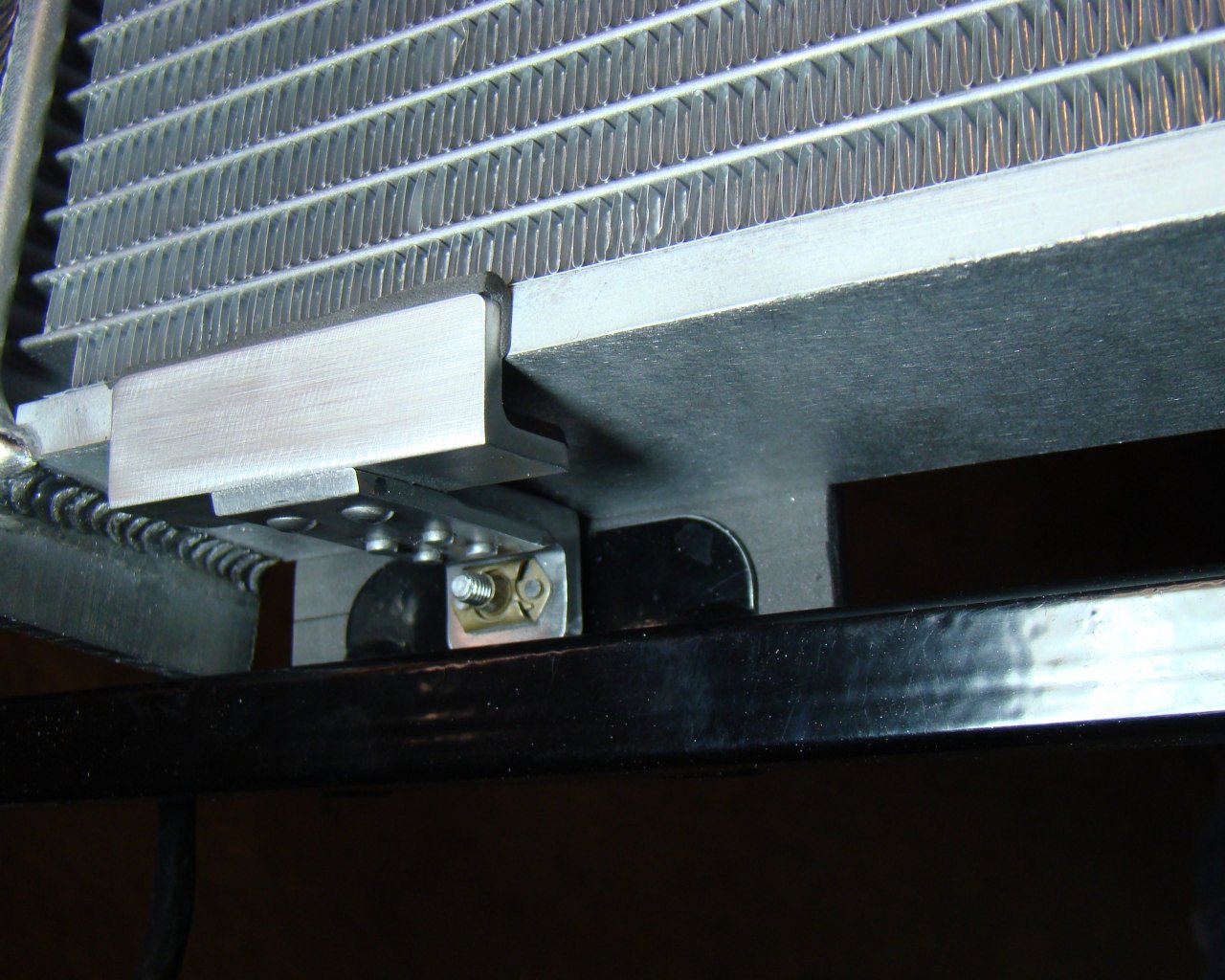
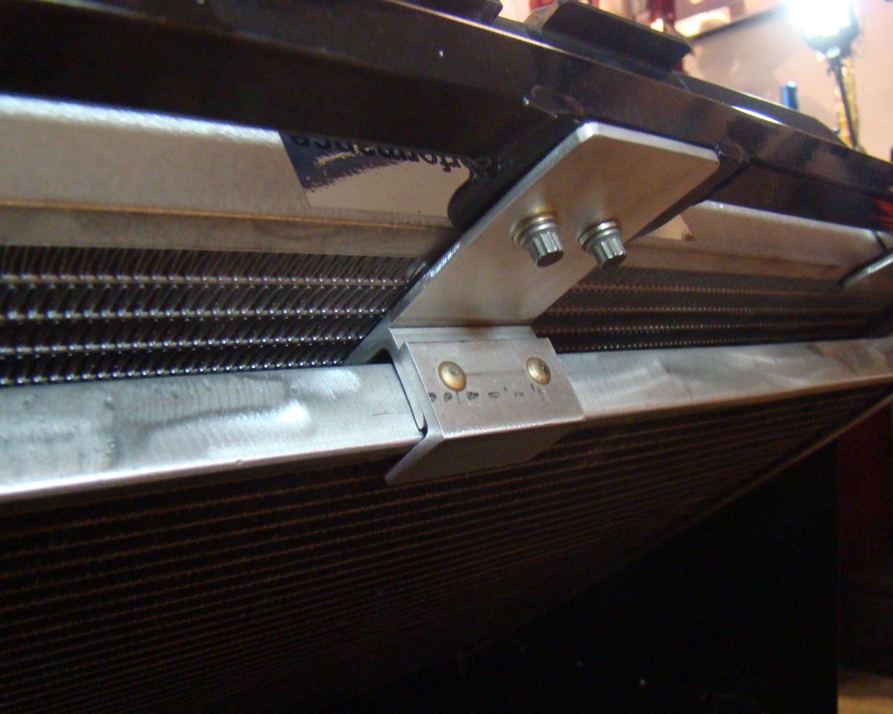
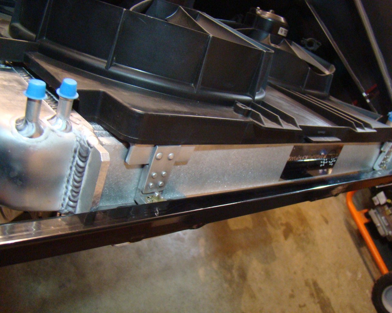
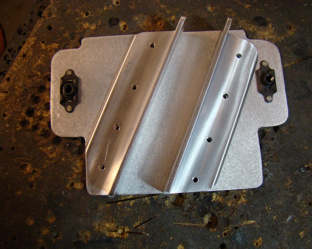
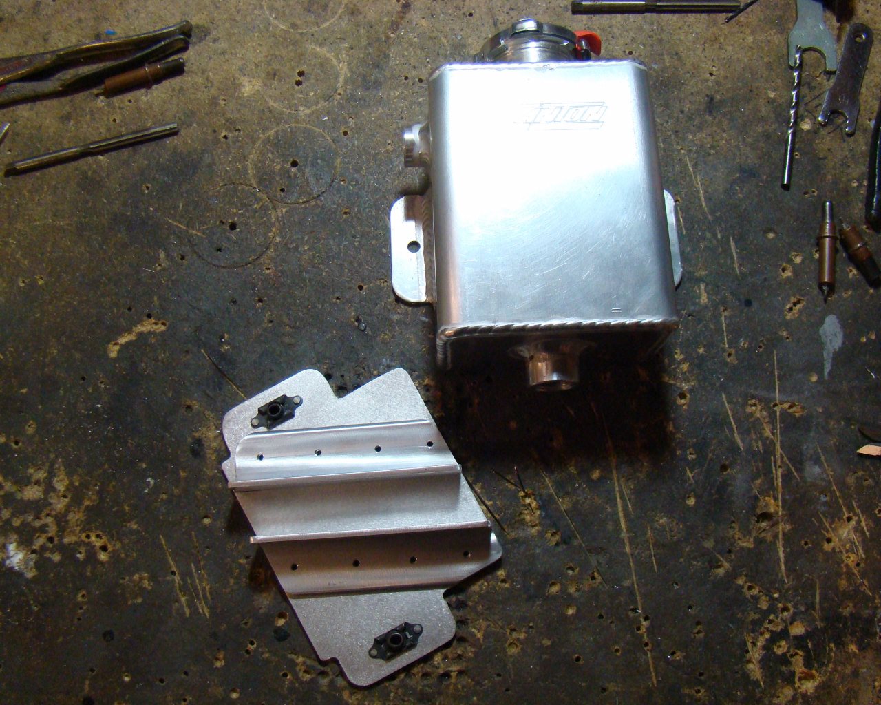
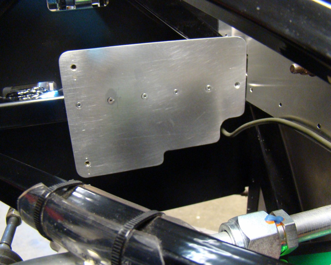
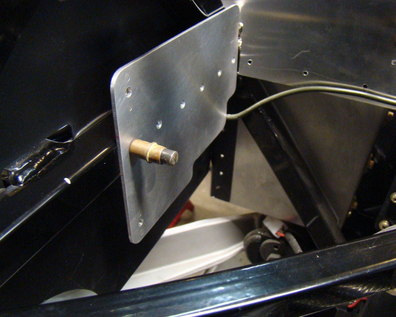
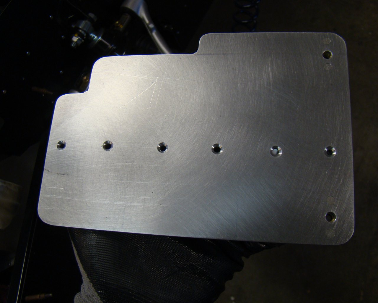
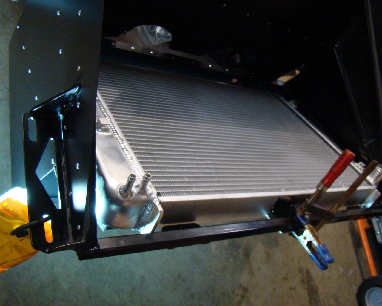
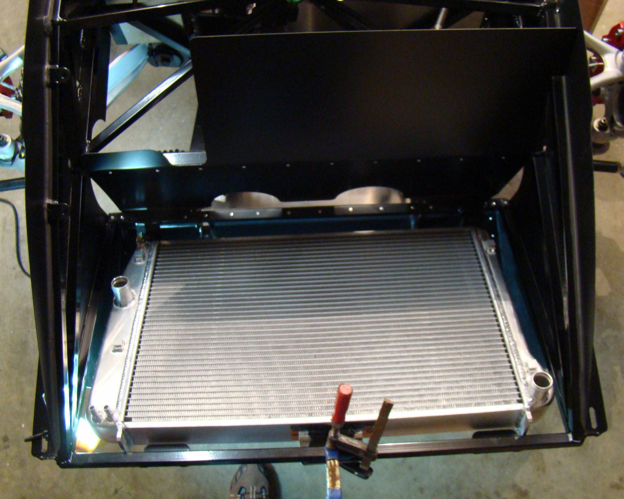
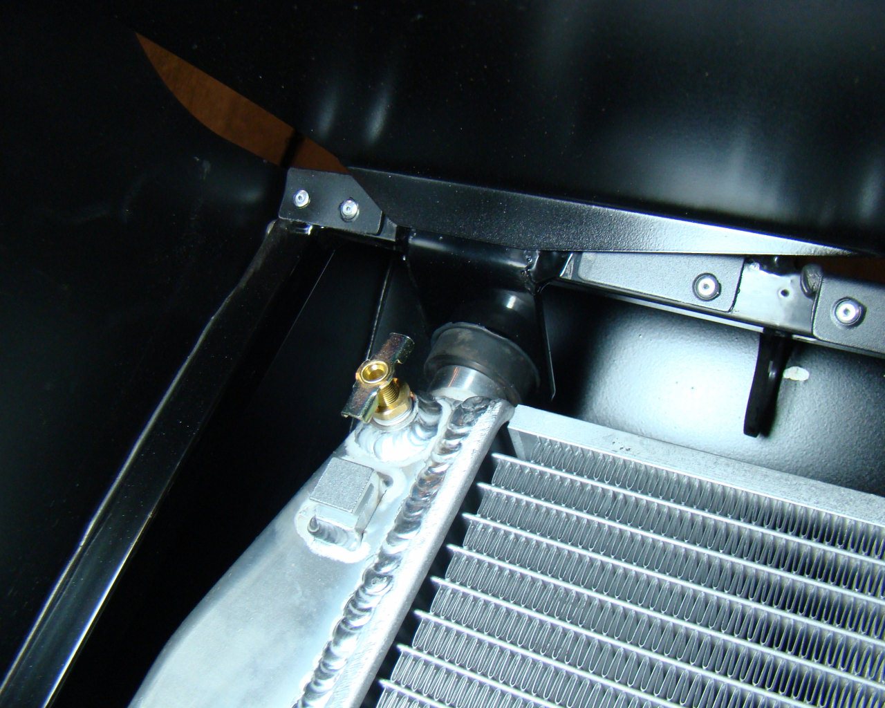
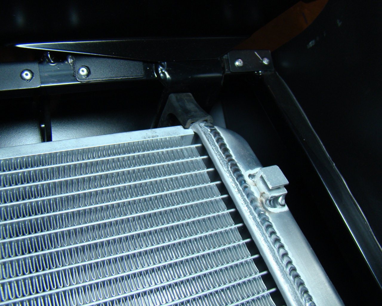
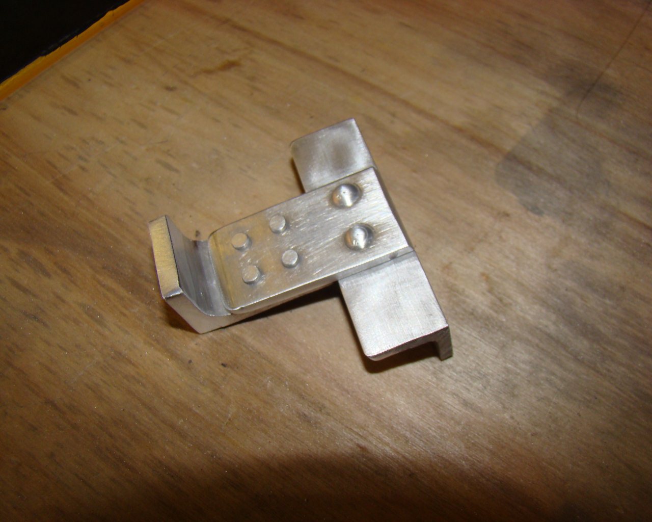
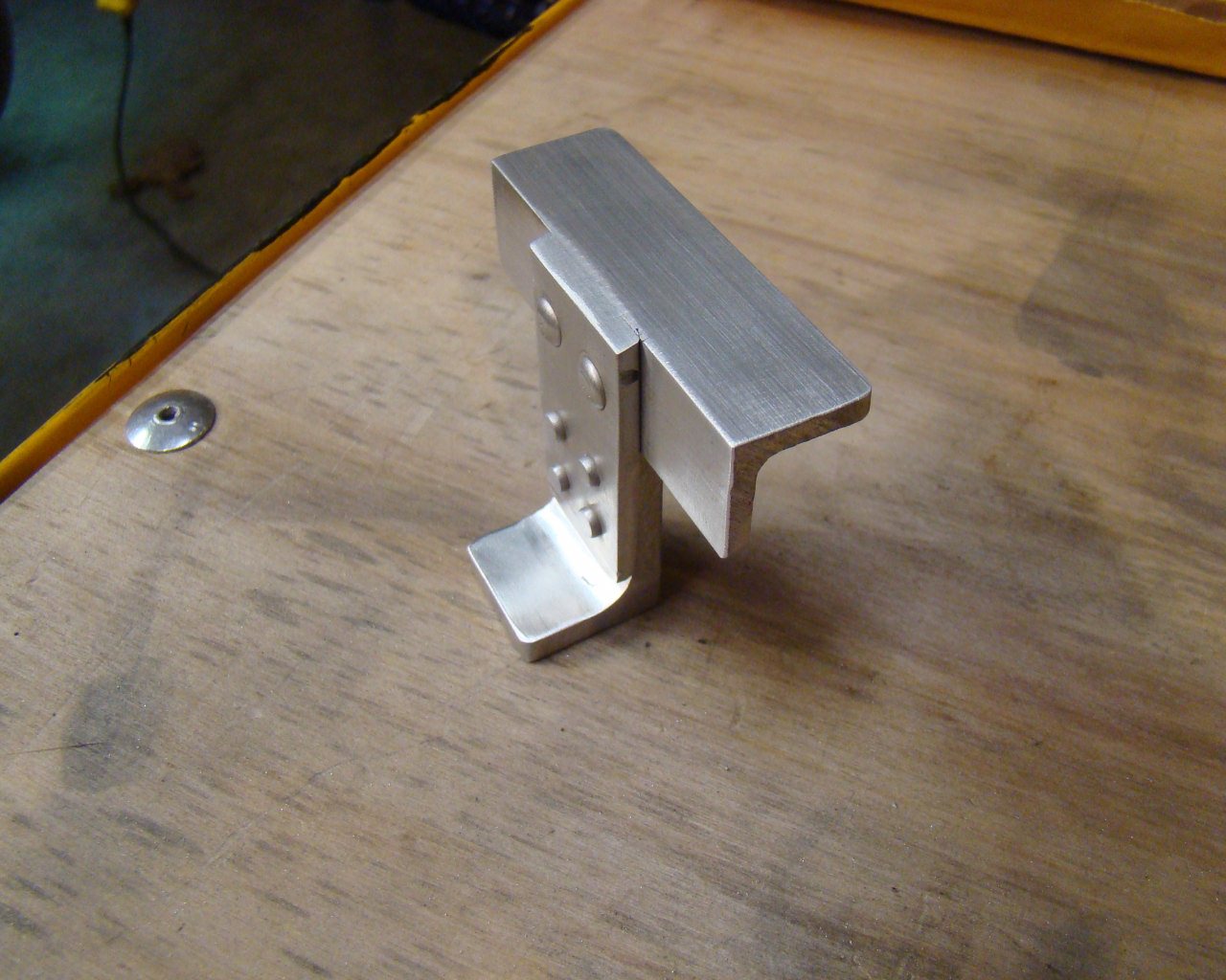
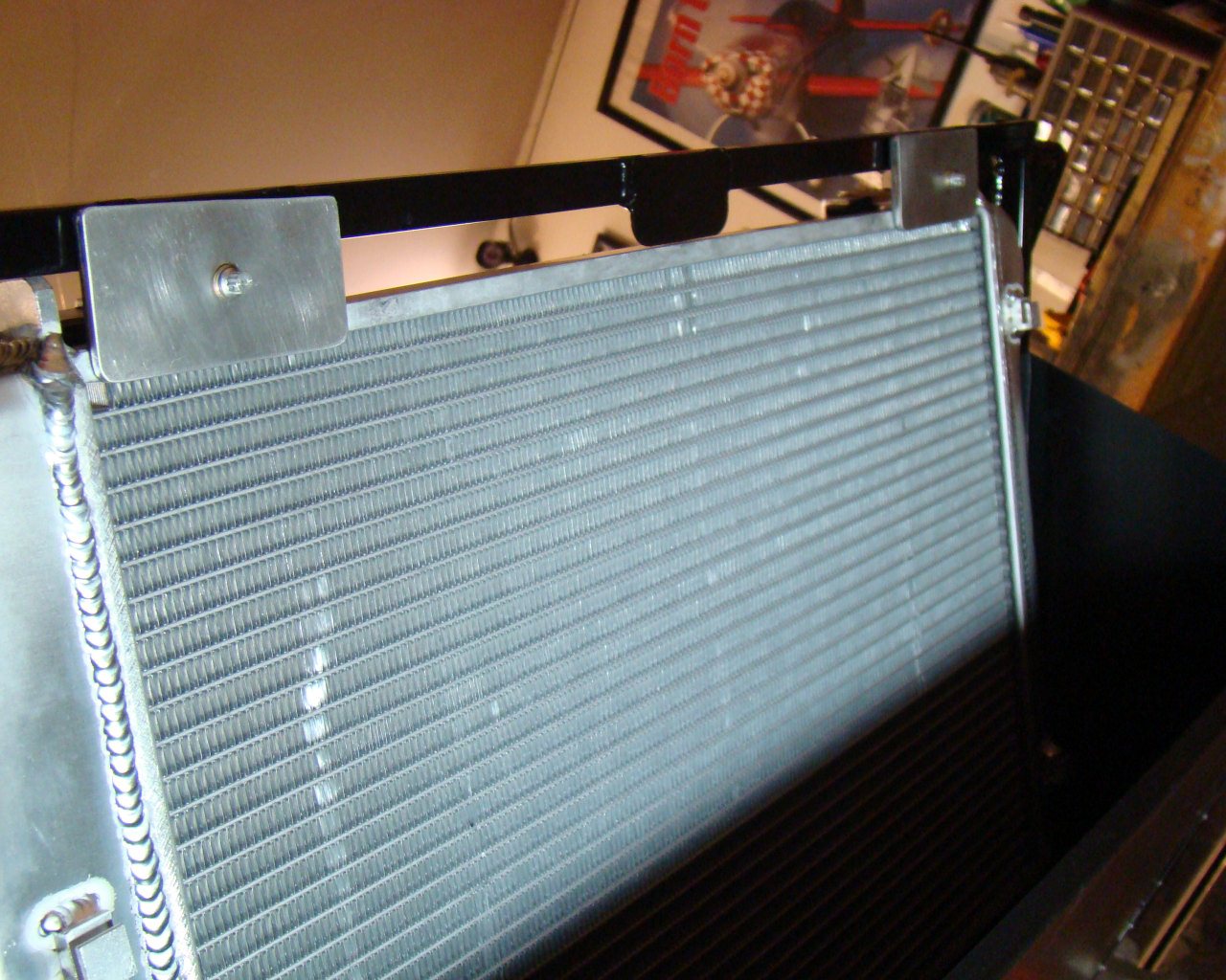
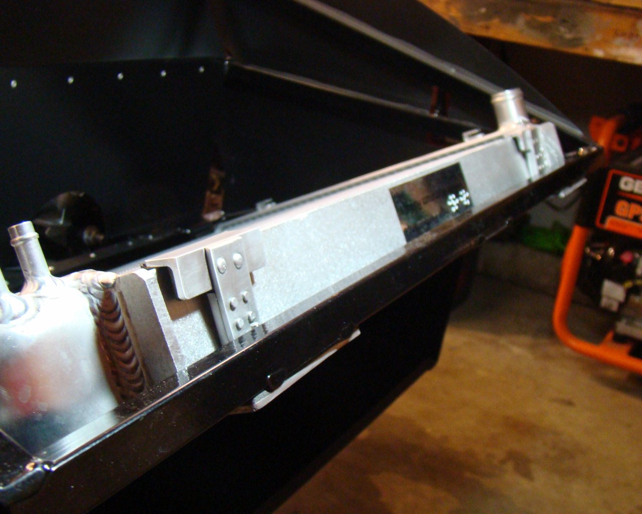
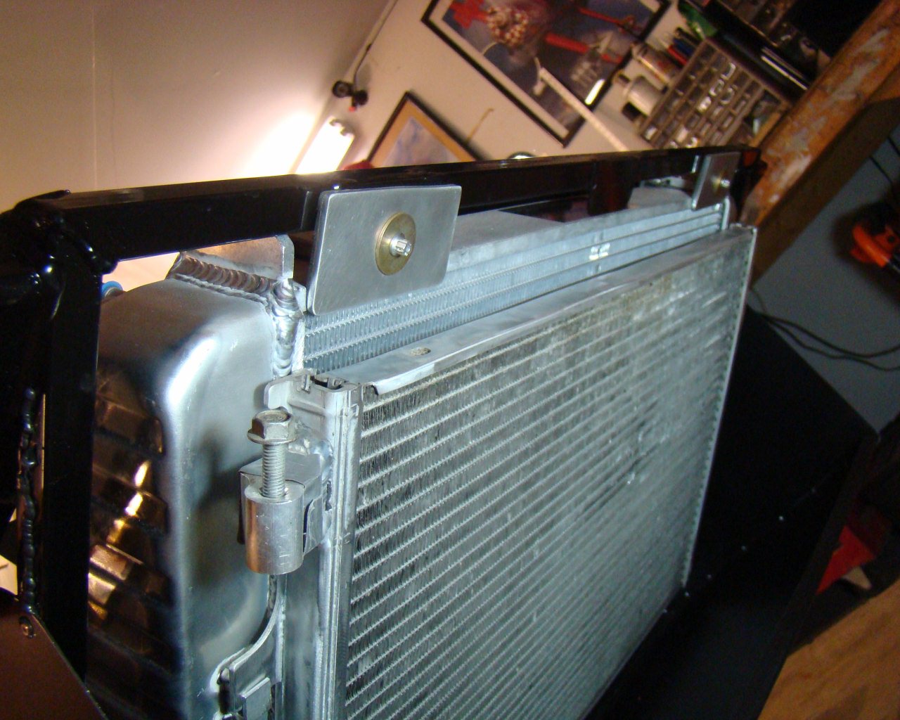
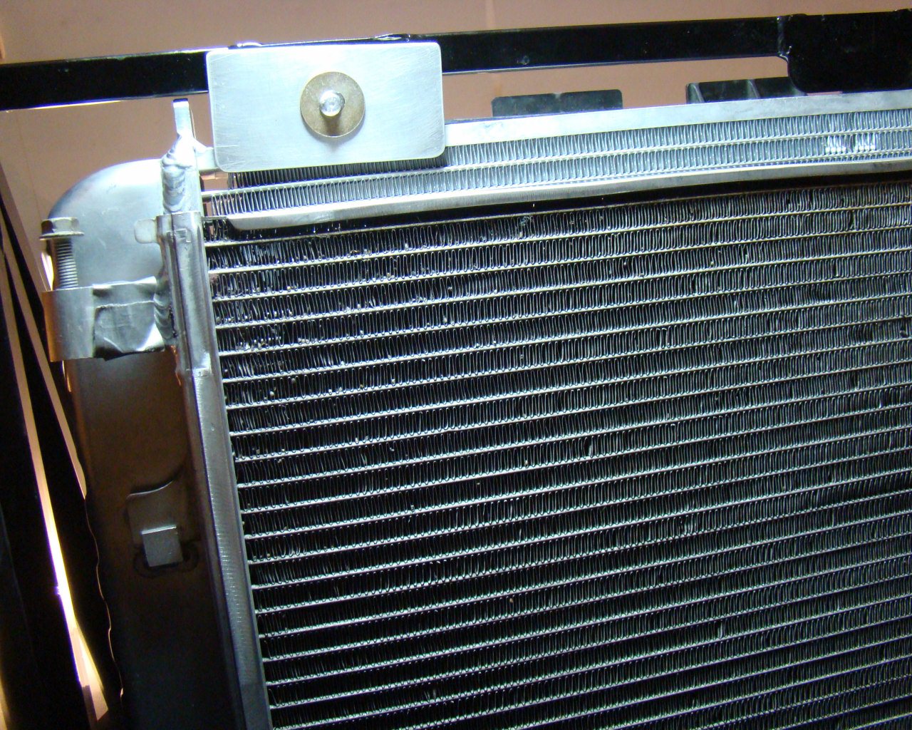
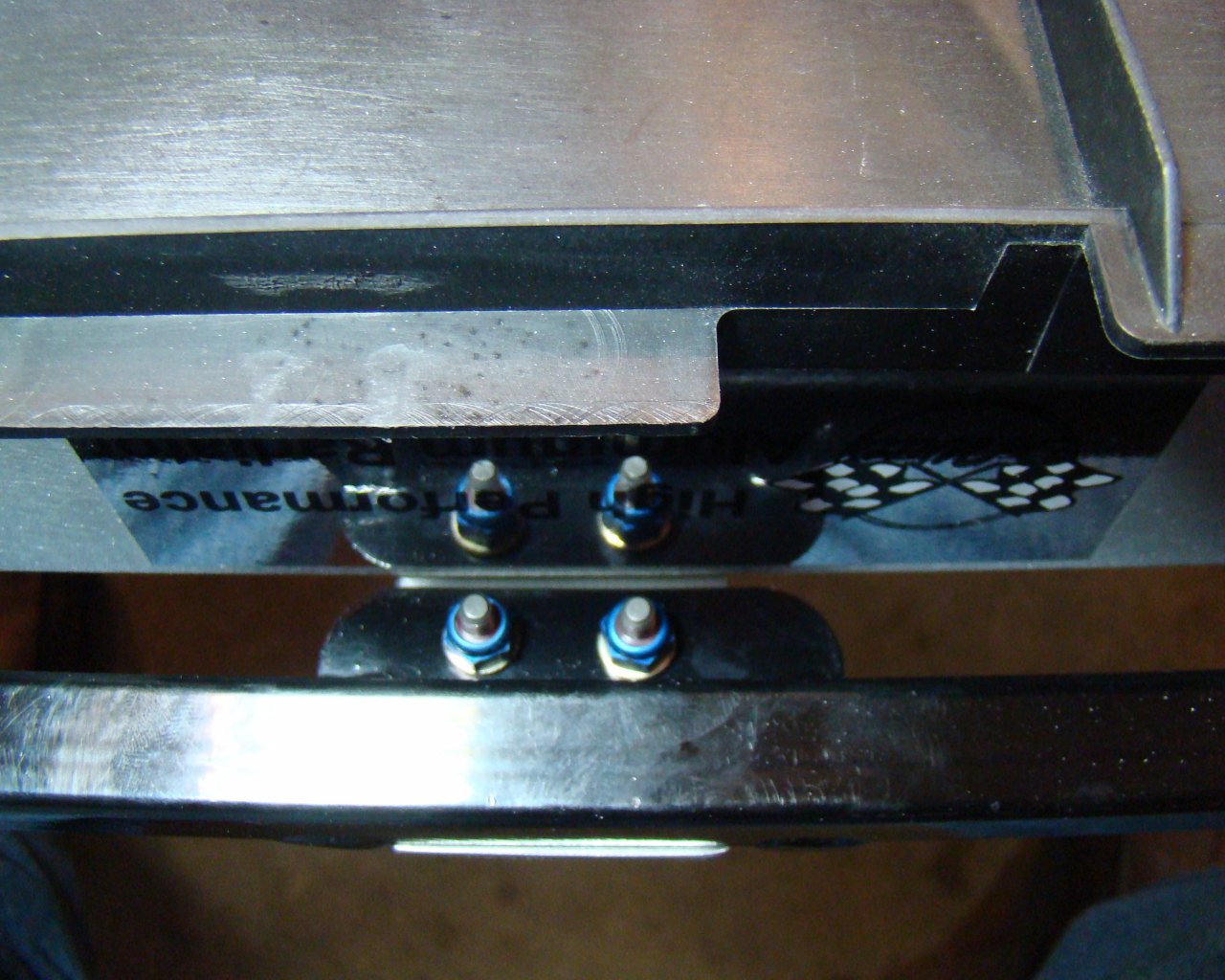
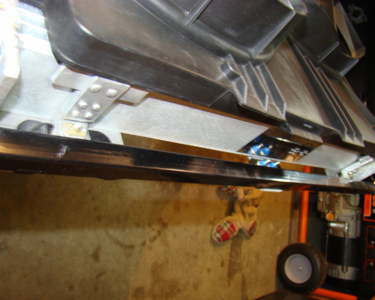
Further down (Way down), you can see how these brackets were fabricated and installed. These brackets engage the tabs on the GTM frame and work perfectly to mount the radiator and condensor coil without the need to TIG weld. They are made from .125 aluminum plate and extrusion riveted back to back with countersunk and/or double-flush aircraft rivets.( MS20470AD 5-4 and MS20426AD5-4)
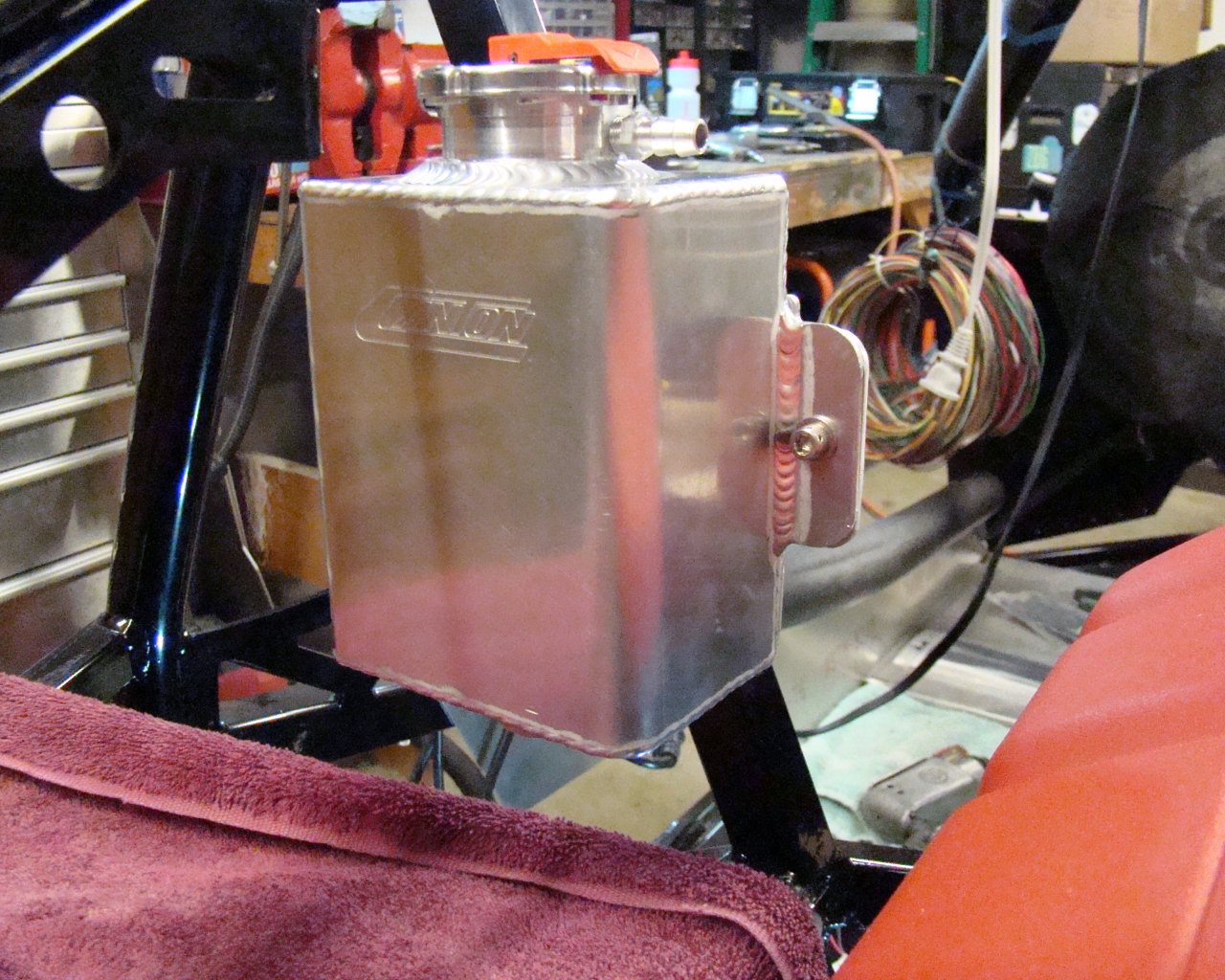
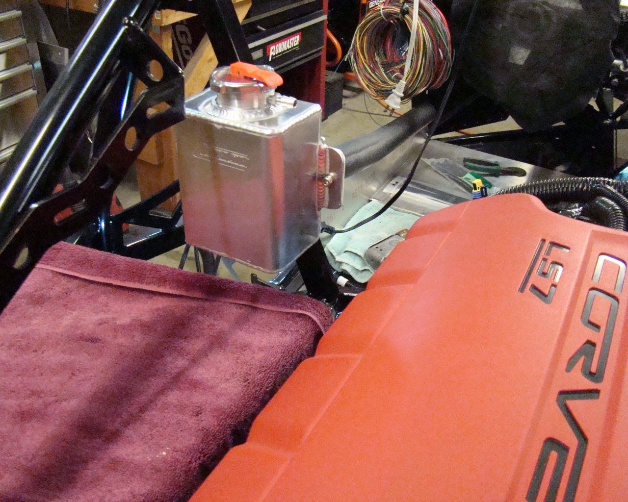
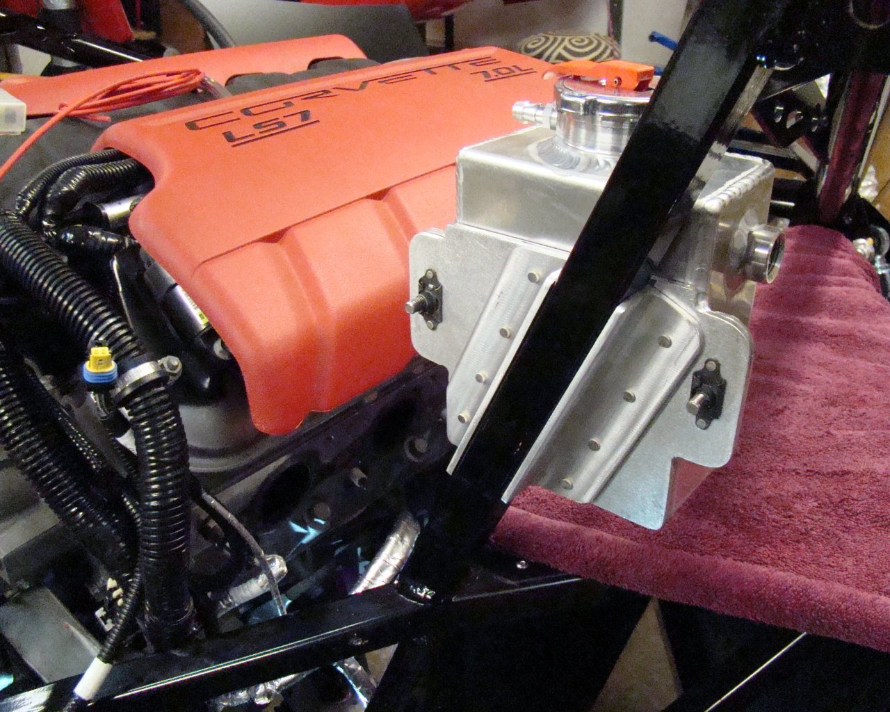
CANTON TANK AND HEATER BYPASS VALVE INSTALL:
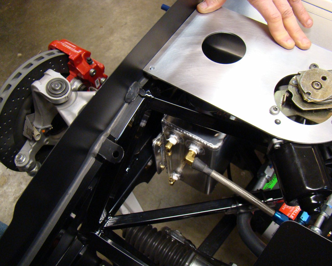
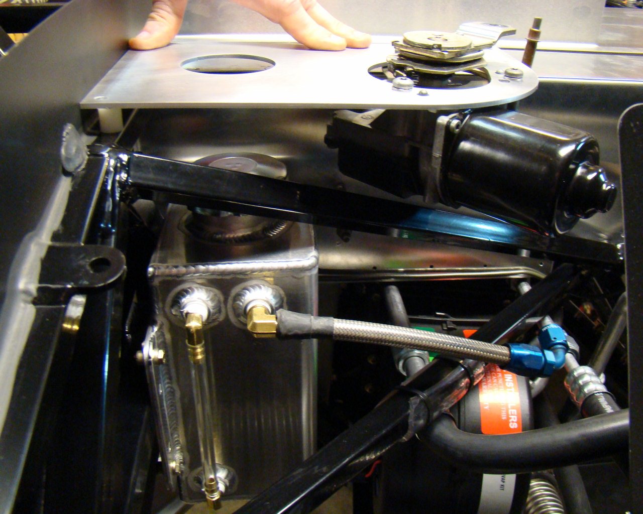
I decided to go with the Canton Expansion tank from Summit racing and heater bypass valve setup from "Crash" at "My Race Shop". These were recommendations and seem to be the hot tip for keeping the expansion tank at the proper level near the engine and also having proper operation of the heating system. Some guys use an overflow tank as well. I decided to purchase a second Canton tank to be an overflow reservoir up front. Its a simple overflow tank with site gauge and a petcock drain. The photos below show how I mounted it after verifying it would fit with the wiper motor mounted. I'm still waiting for components for the engine oil and fuel system so I'm not quite at the point I want to drop the engine in the chassis. Also, I've got the LS7 standalone wiring/ECU setup on the way and will be doing some prewiring prior to engine installation.
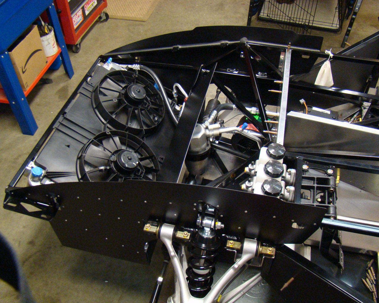
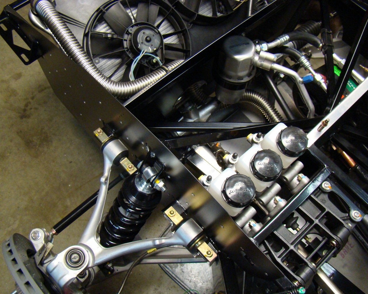
On to the cooling challenges. I spent considerable time routing lines today. The work today took about 15 hours and included assembly and routing of the Aluminum "Hard" coolant lines and fabrication of clamp brackets to secure the coolant and A/C lines that run through the "tunnel" in the middle of the car. There were no particularly difficult areas here but I did take extra time measuring and positioning clamp locations. I fabricated several L-Angle brackets with Nutplates to facillitate easy installation of all lines through the tunnel. They are clamped, spaced and positioned in a way that prevents interference and chafing. See below.
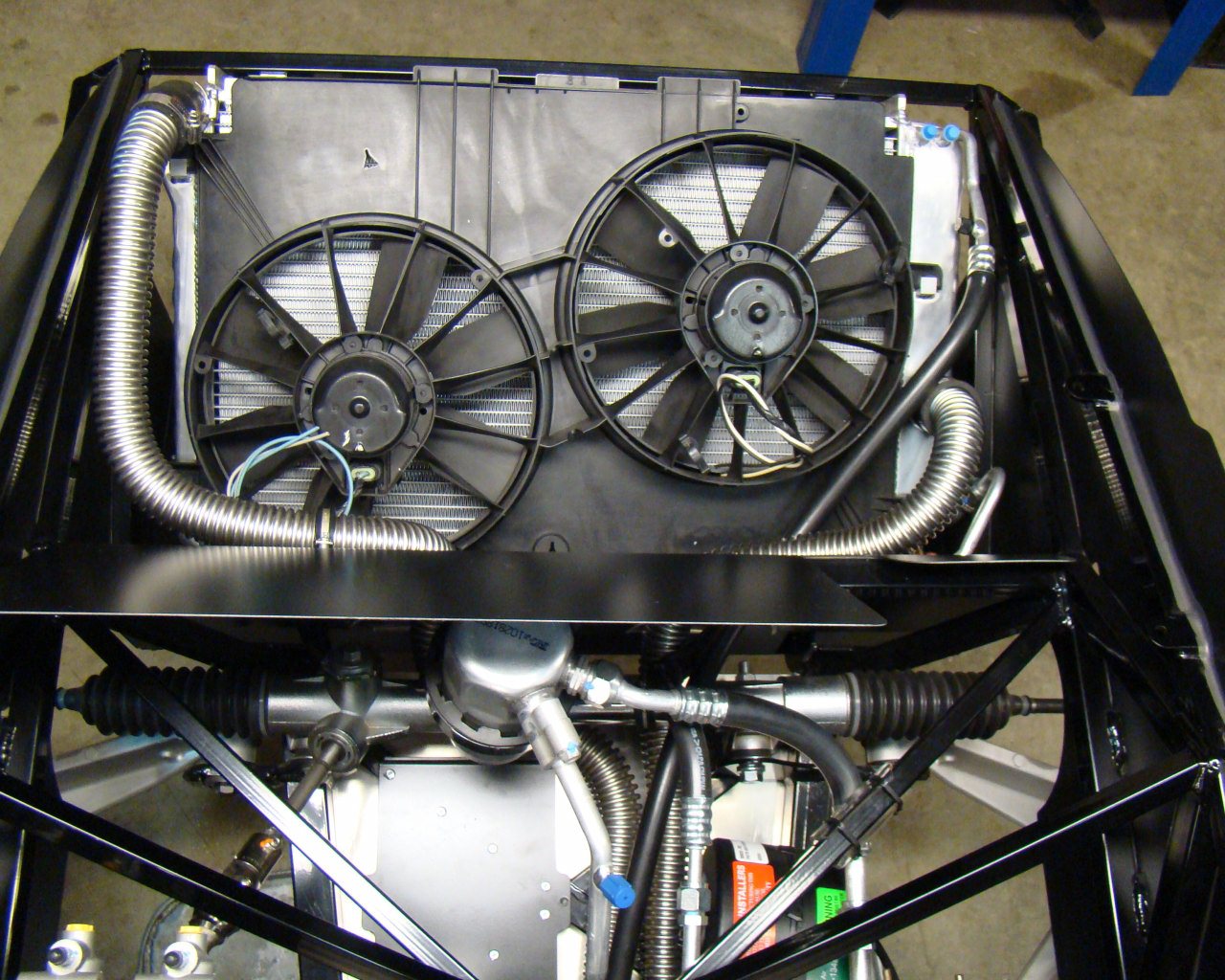
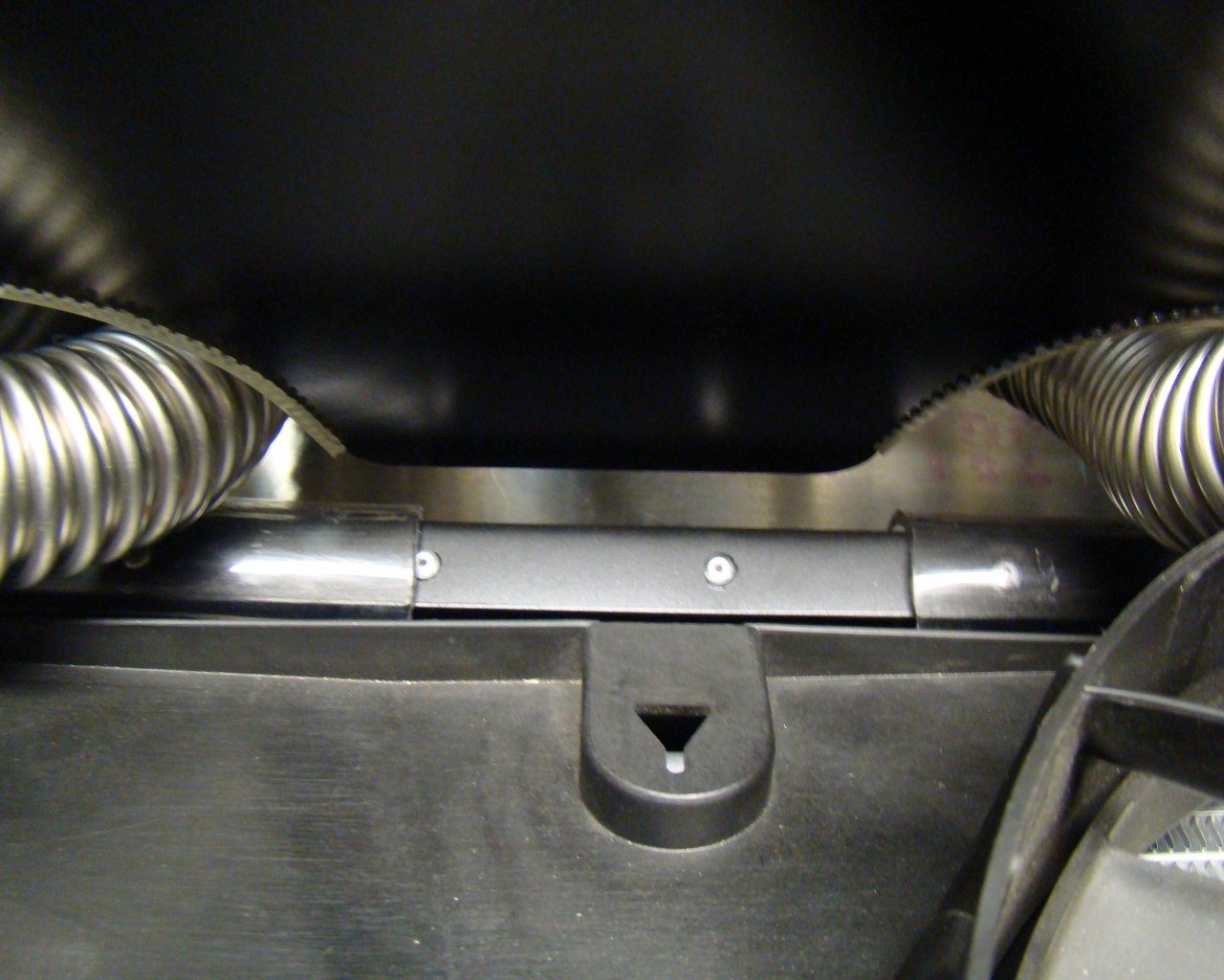
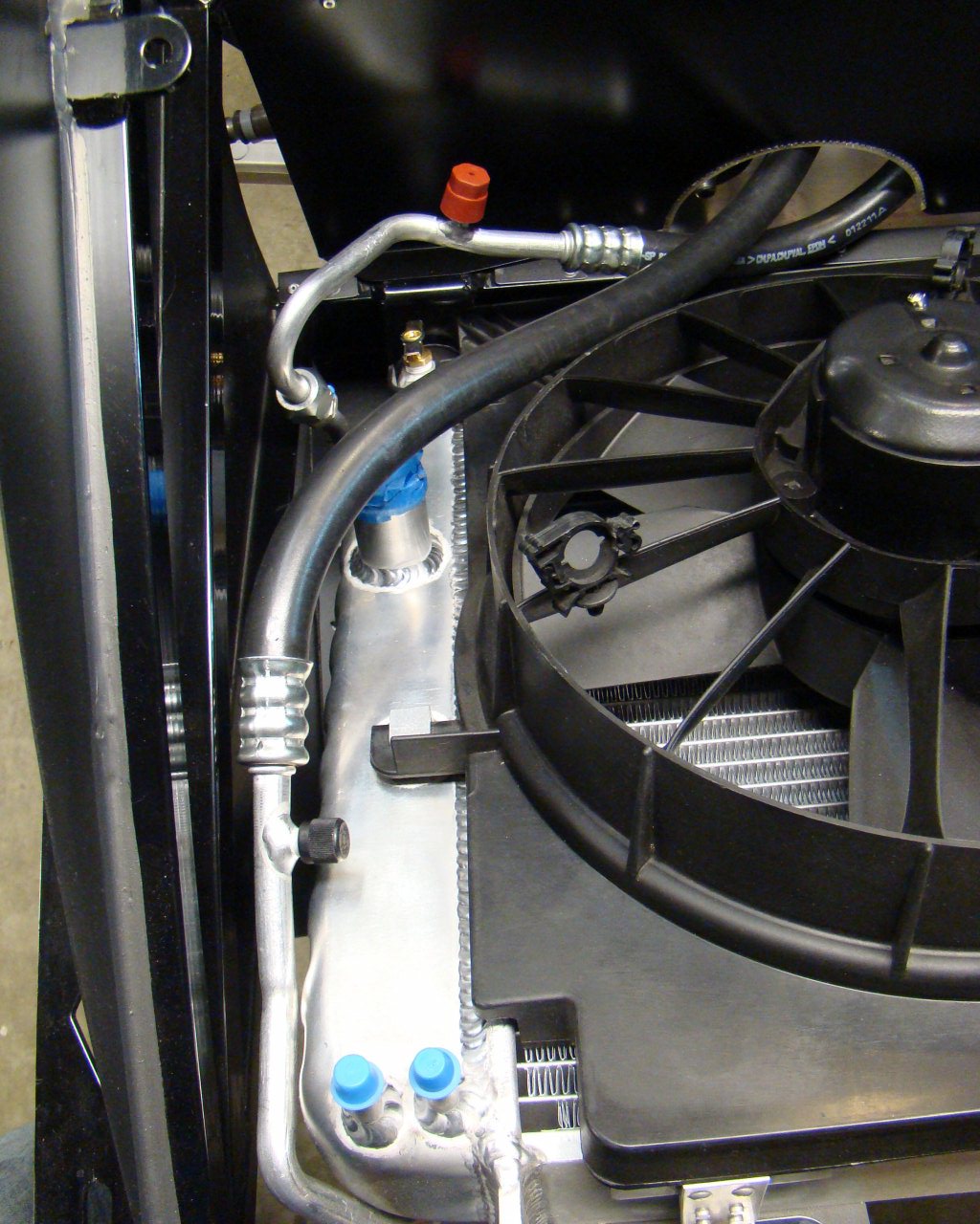
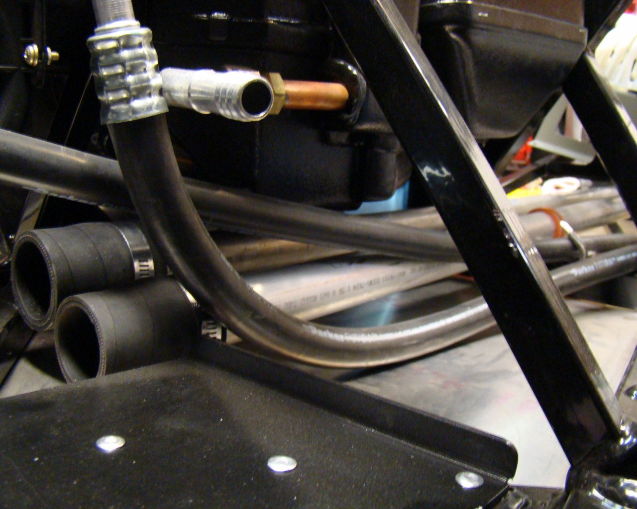
Notice the Anti-Chafe "chicken track" and the clear poly tubes that
prevent rubbing of the coolant hoses with the surrounding structure
and components.
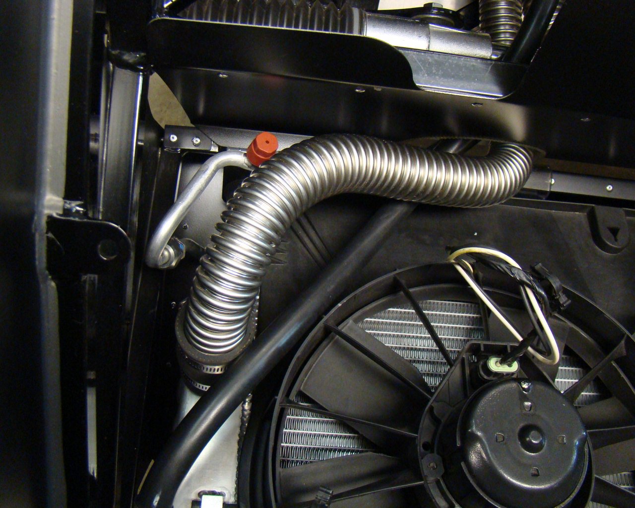
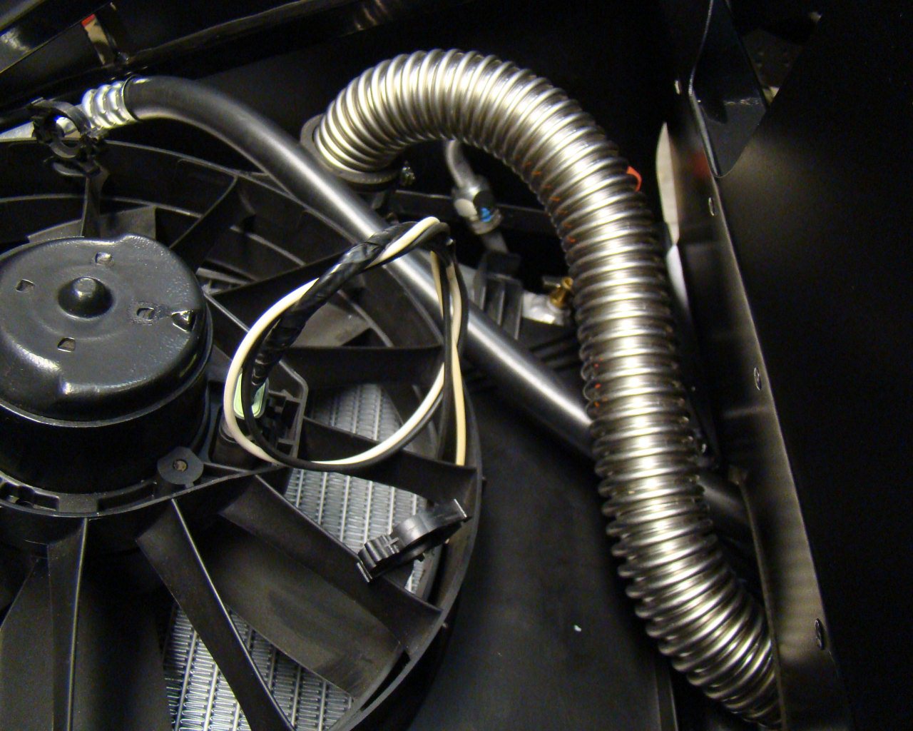
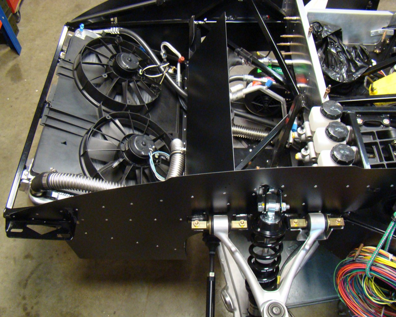
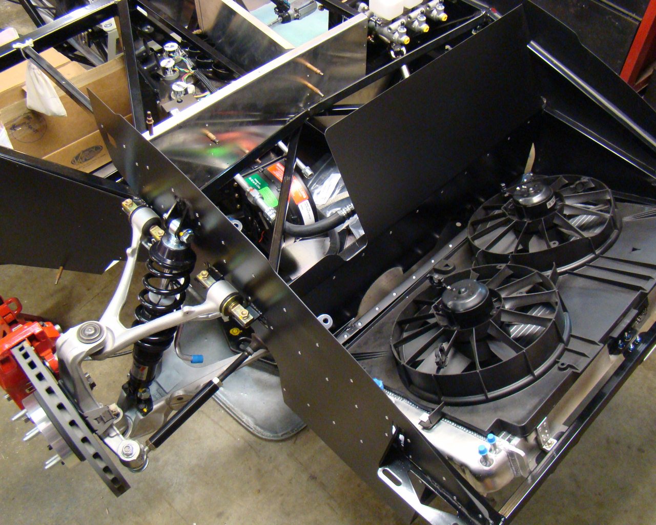
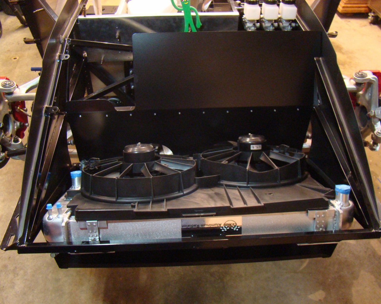
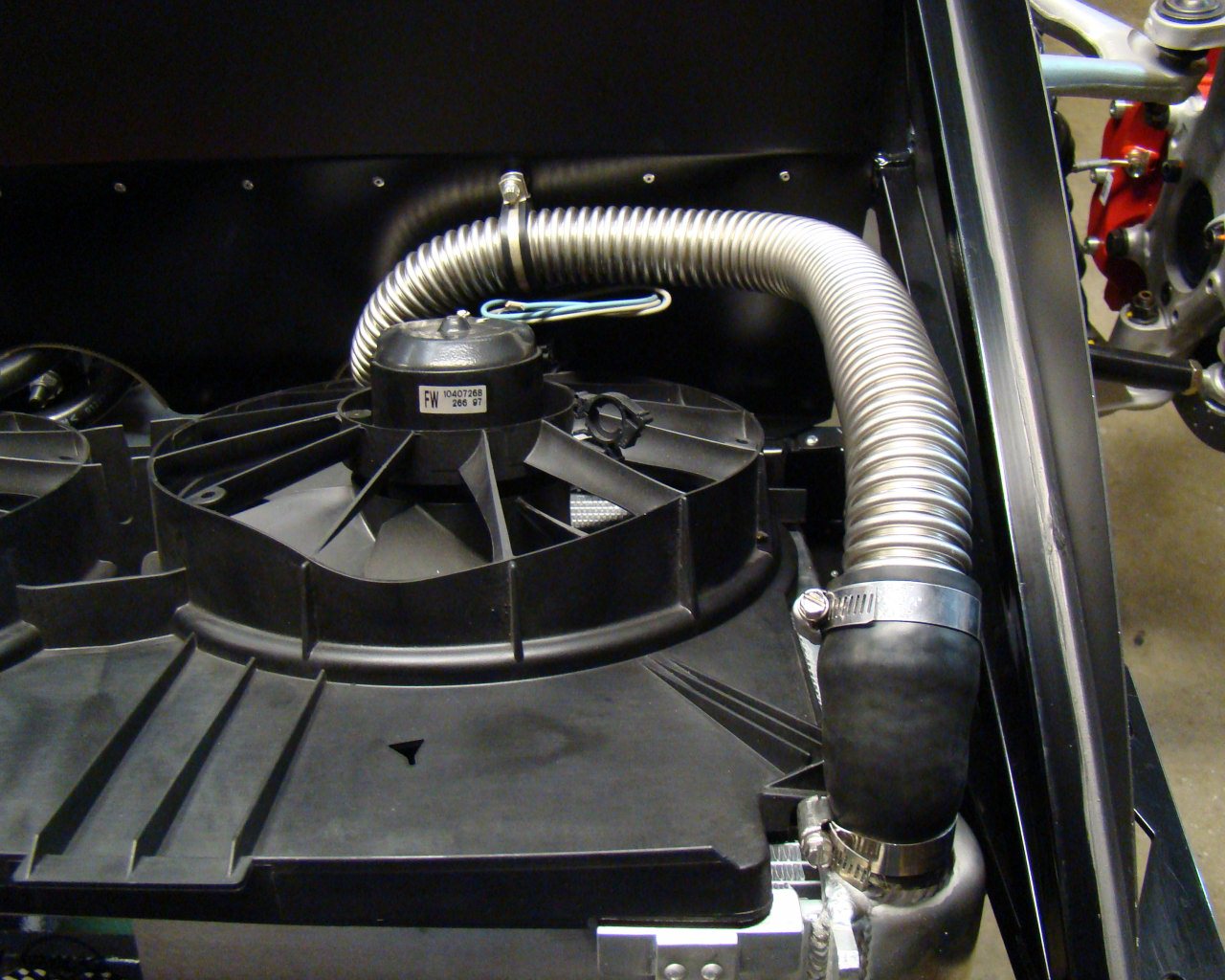
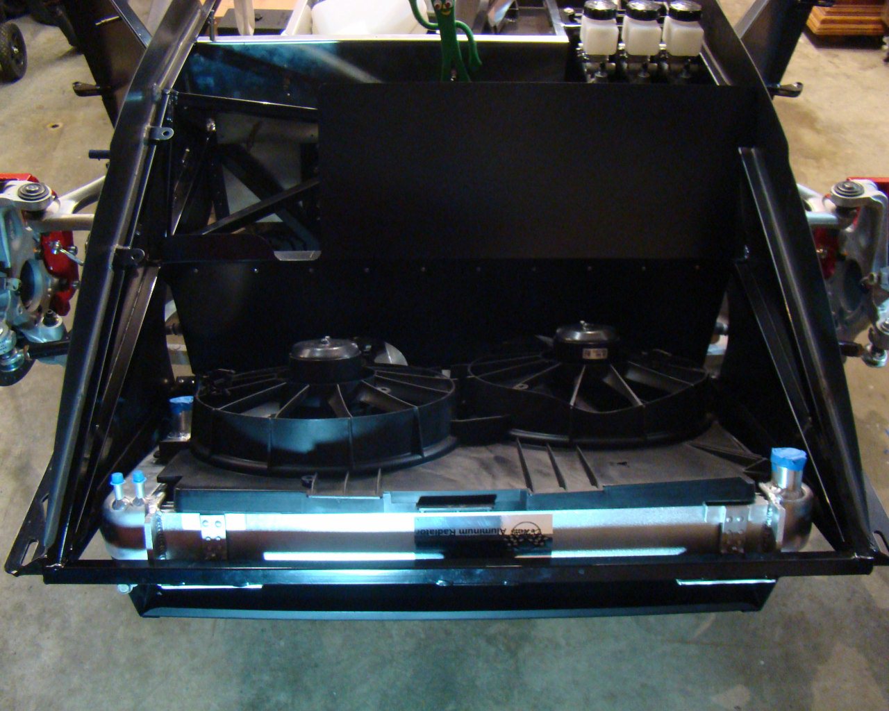
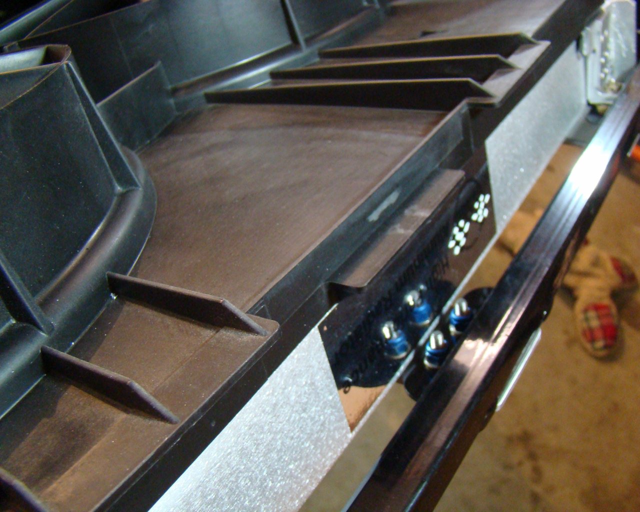
Notice the cutout in the Fan
Shroud. This was necessary due to the coolant line position
coming out from under the panel. No matter how I twisted and
repositioned the line, it was touching the sidewall of the fan
shroud. Finally I decided to trim the shroud, removing one
plastic stiffner from it's frame. This worked
perfectly. Also, I turned a rivet hole into a Rivnut hole and
used a 10/32 bolt to fasten the upper radiator coolant line.
This kept the line in the proper position to the extent it touches
nothing until it gets to the hard coolant line in the compartment
behind the panel.

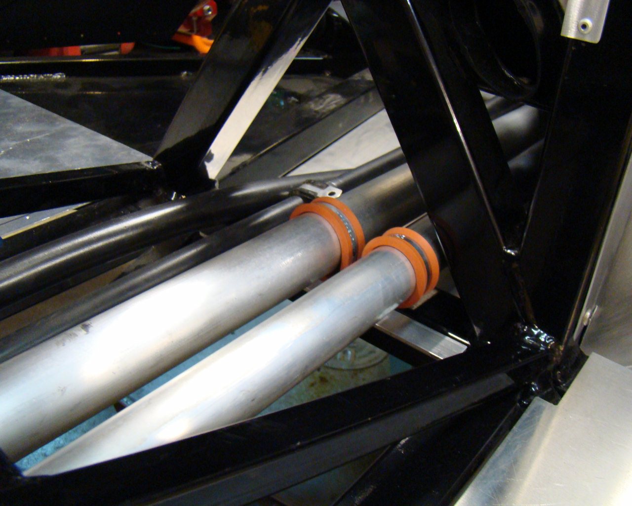
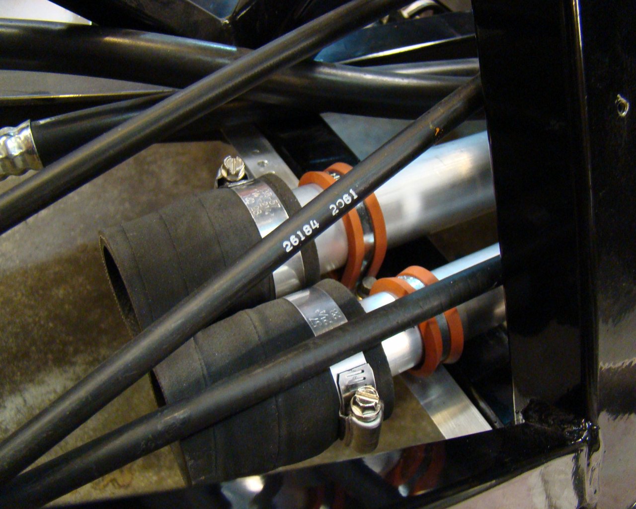
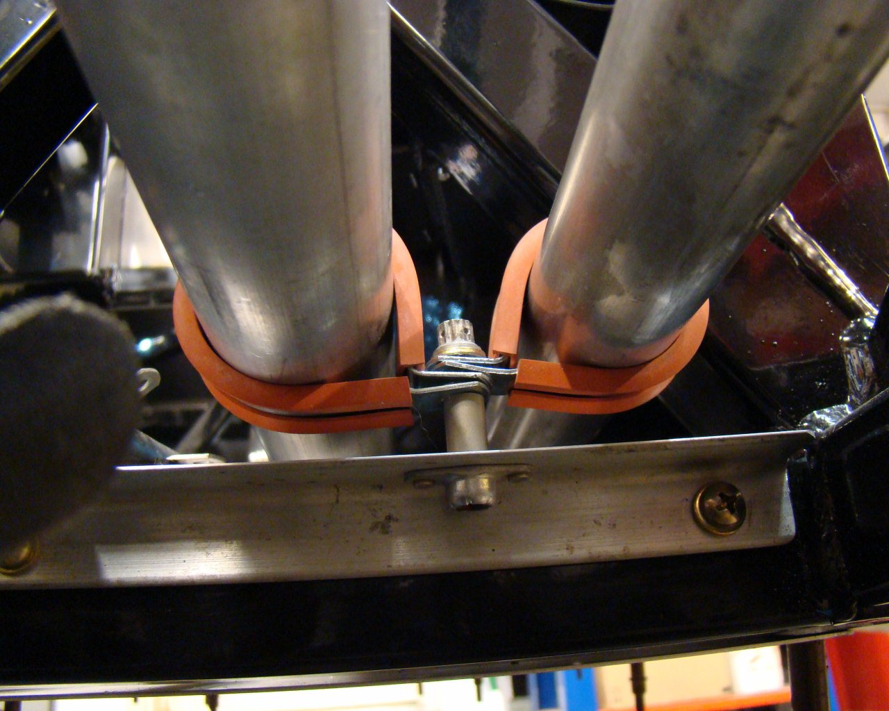
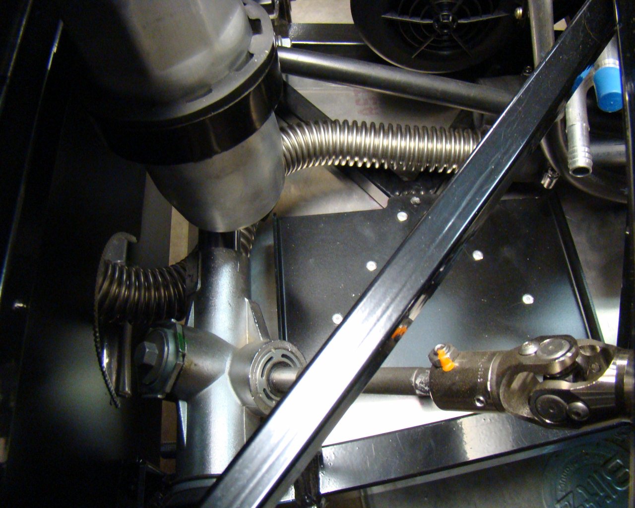
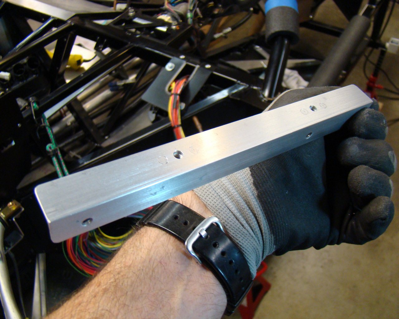
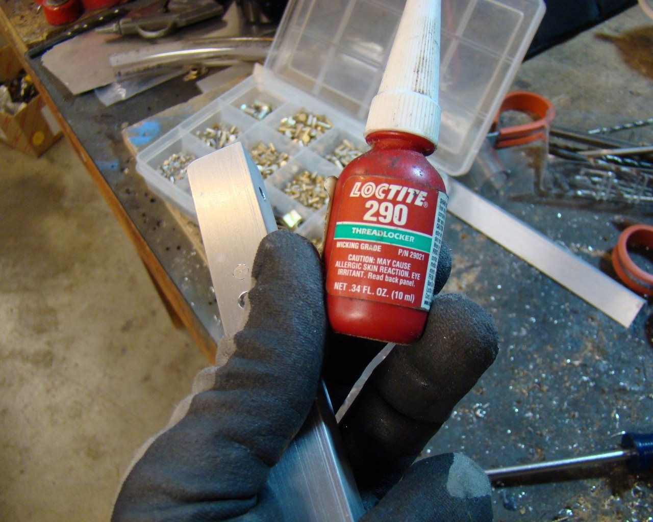
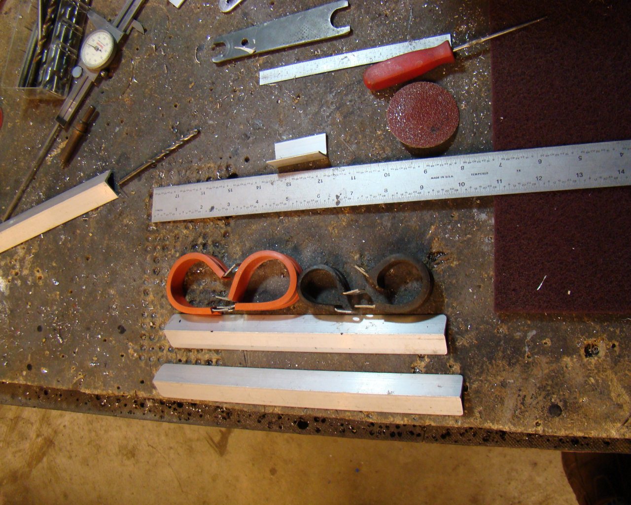
To get the hard lines in securely, I decided to fabricate aluminum L-angles with clamp standoffs for the hard aluminum and A/C compressor lines. This was pretty easy and it will make maintenance easier down the road. The L angles are fabricated with .063 T3 aluminum L-angles with nutplates attached to the flanges. I measured the frame cross section and cut these to length and then used Rivet Nuts in the frame to attach the angle. I used standoffs (approximately .375" to space the coolant line clamps up a little to avoid interference with the frame "X" near the battery. See below. The Threadlocker (LocTite) 290 is specifically used for fasteners exposed to vibration. This lessens the chance of things getting loose and falling out later.
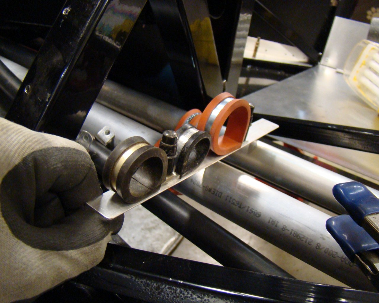
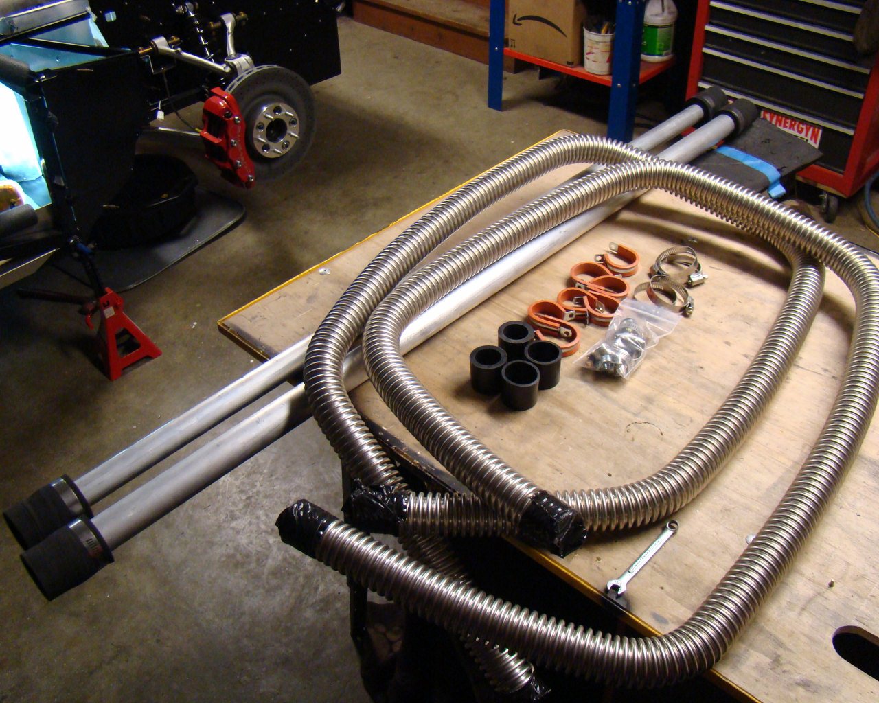
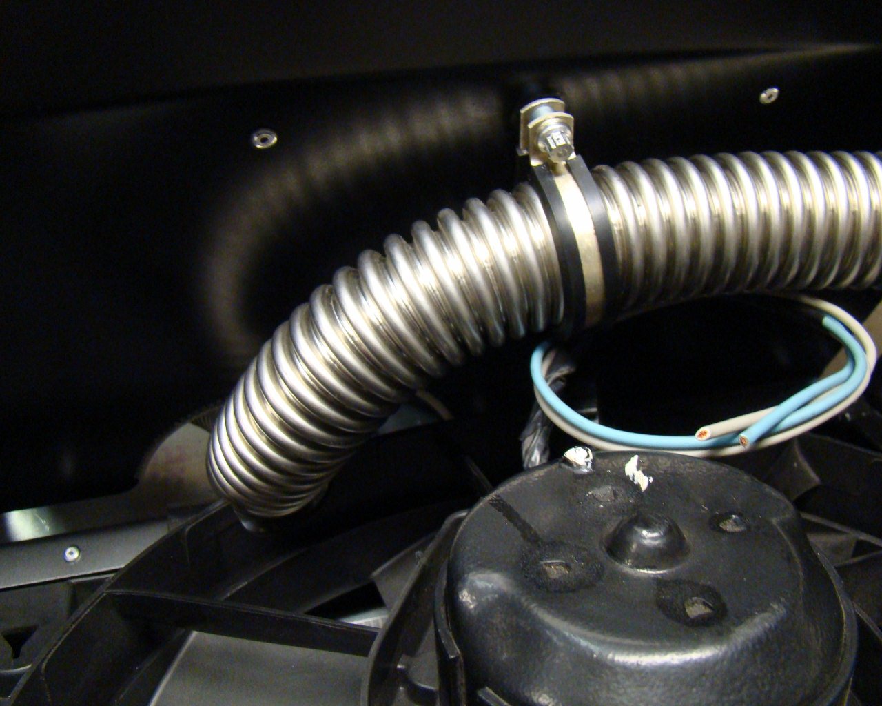
Below you see the Aluminum cooling tube adapter hoses. There should be seven (7) kits (35 total pieces) just for the hose adapters and metal clamps.
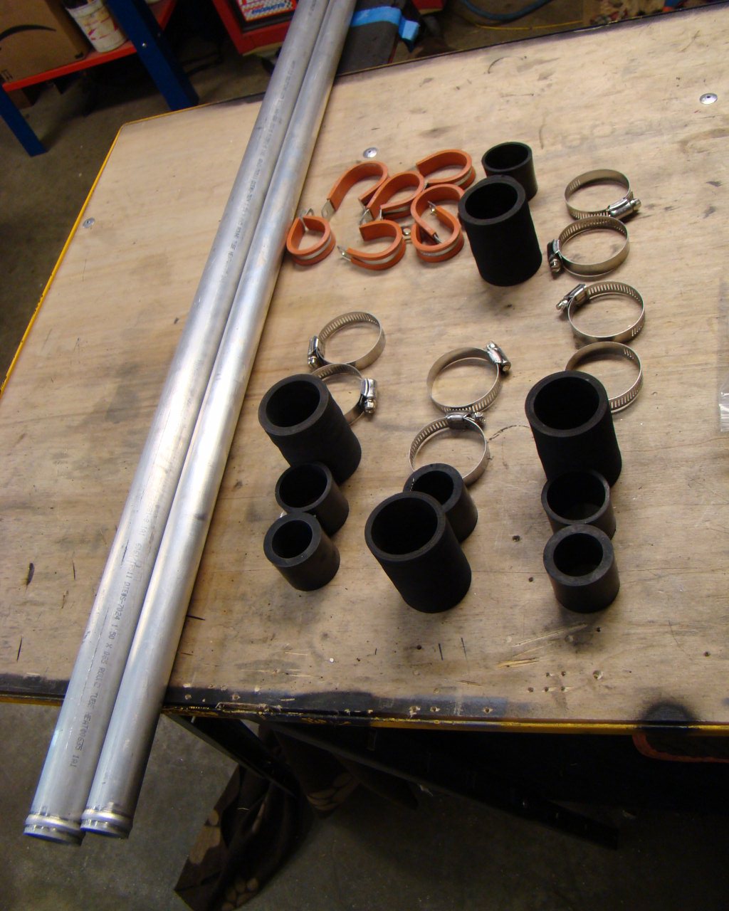
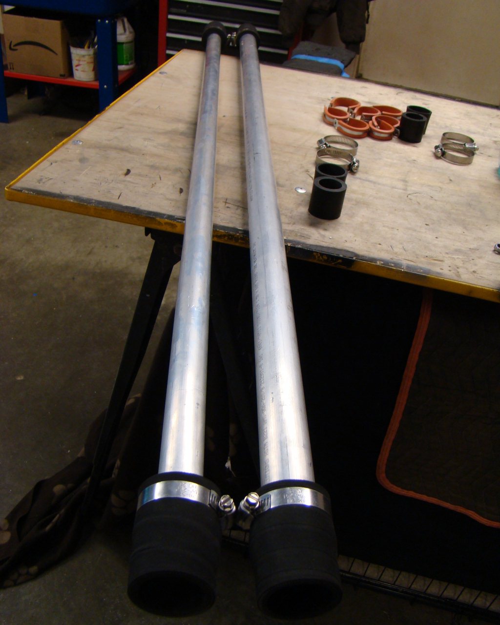
BTW - Don't put the cooling tubes in the tunnel and then put the
adapters on. Put them on first and save your back.
There's no reason to hassle trying to do this while they are in the
tunnel. The adapters go on easy with a little soapy
water....as stated in the manual.
2/2/2013 - More AC and
heating stuff. The Evaporator lines and the lines coming
forward through the tunnel from the compressor were fabricated in a
way that makes them difficult to attach to the components.
After moving the accumulator and trying several options (and some
slight tweaking) I got the stuff to mount satisfactory with no
major preload. Just keep moving these around a little at a
time and it will all go together. Like everything else, it
doesn't go exactly as planned.