ELECTRIC
ELECTRIC


THE BELOW PHOTOS AND SEQUENCE DESCRIPTIONS BEGIN AT THE BOTTOM AND
END HERE. TO VIEW PREVIOUS WORK, SCROLL
DOWN.
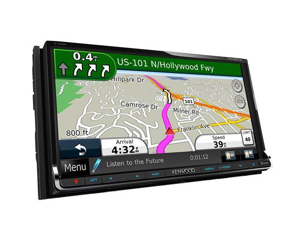
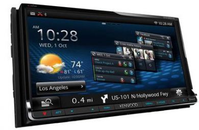
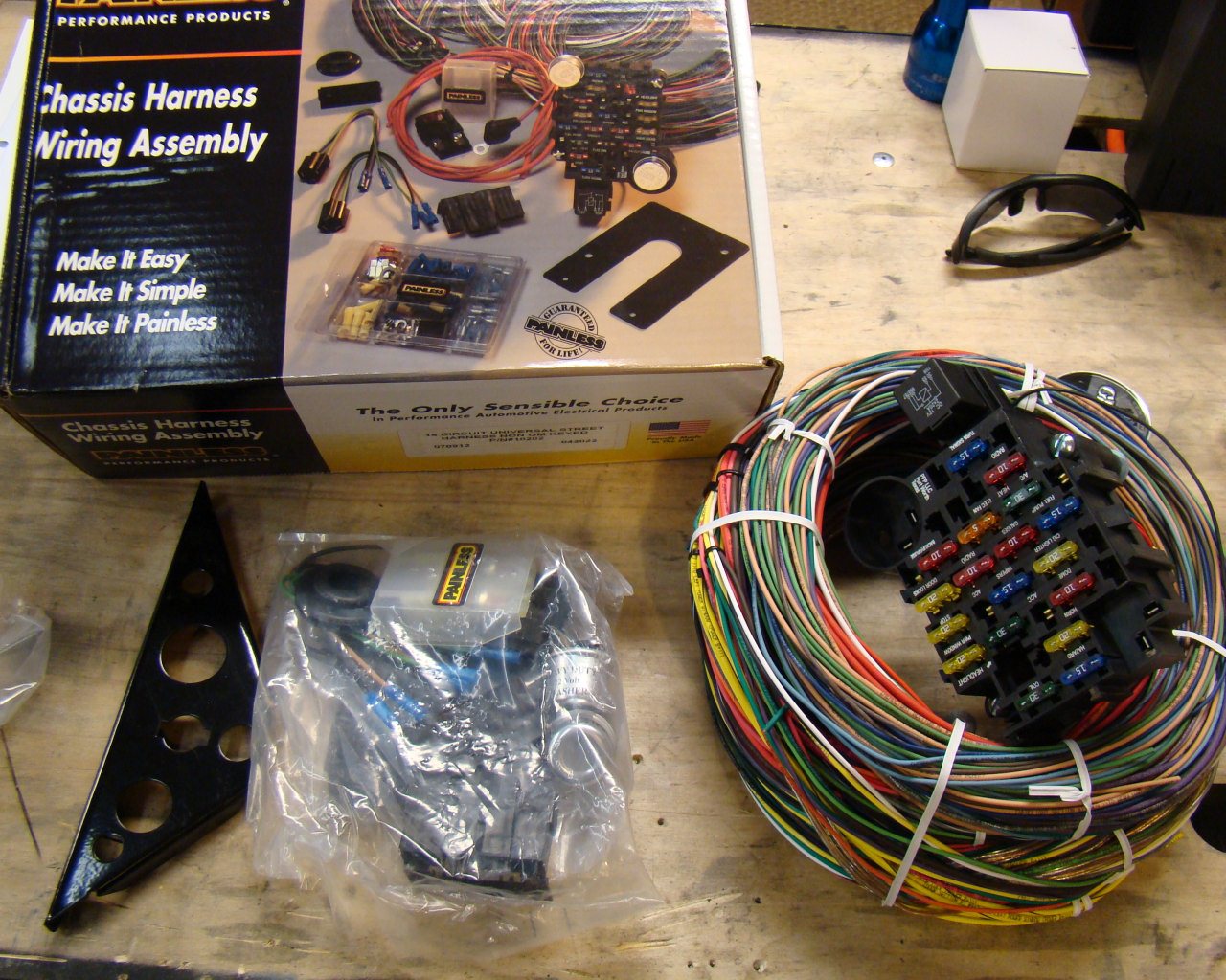
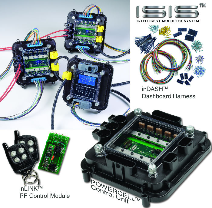
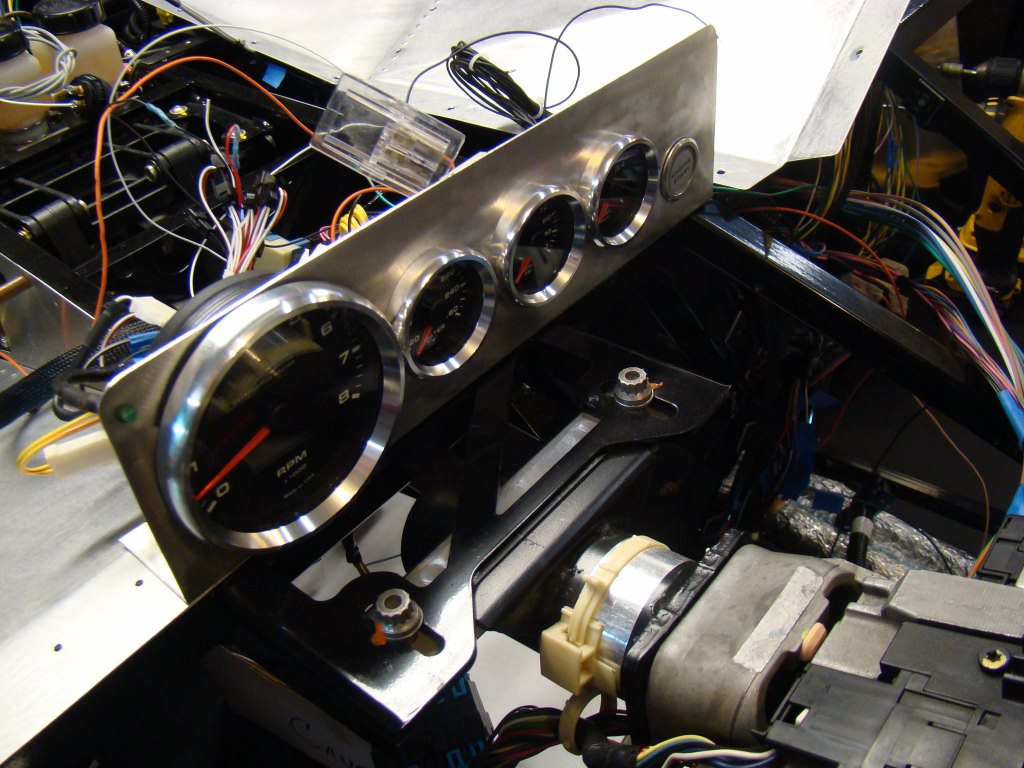
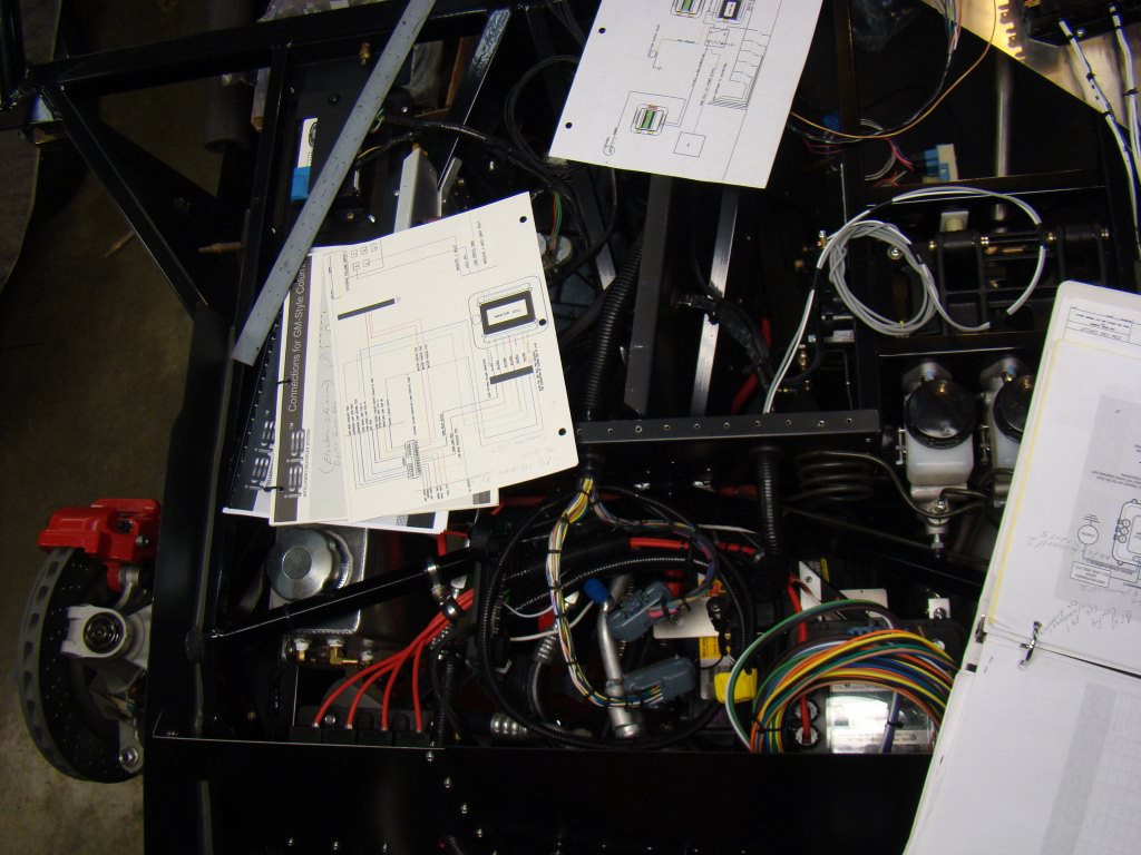
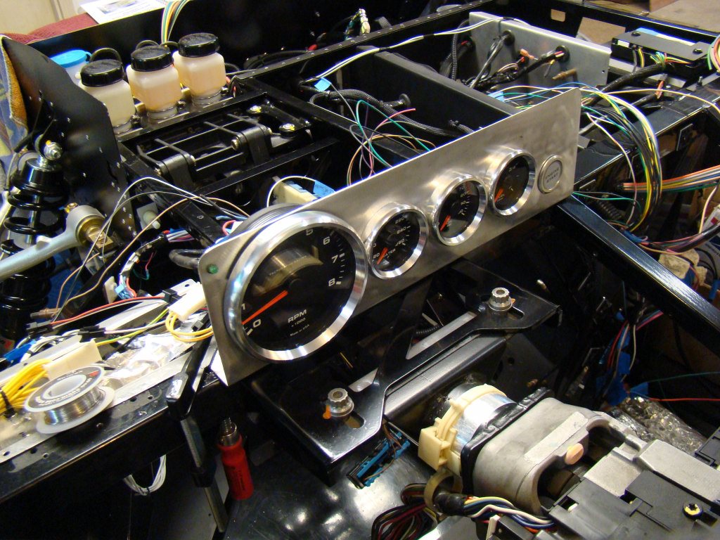
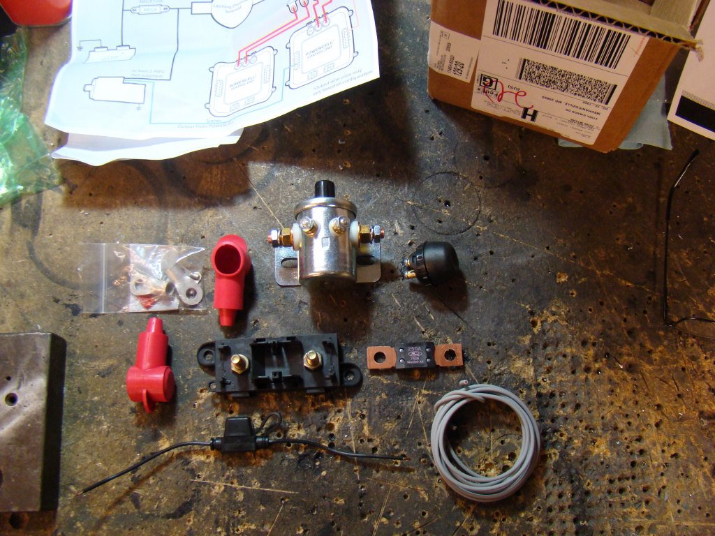
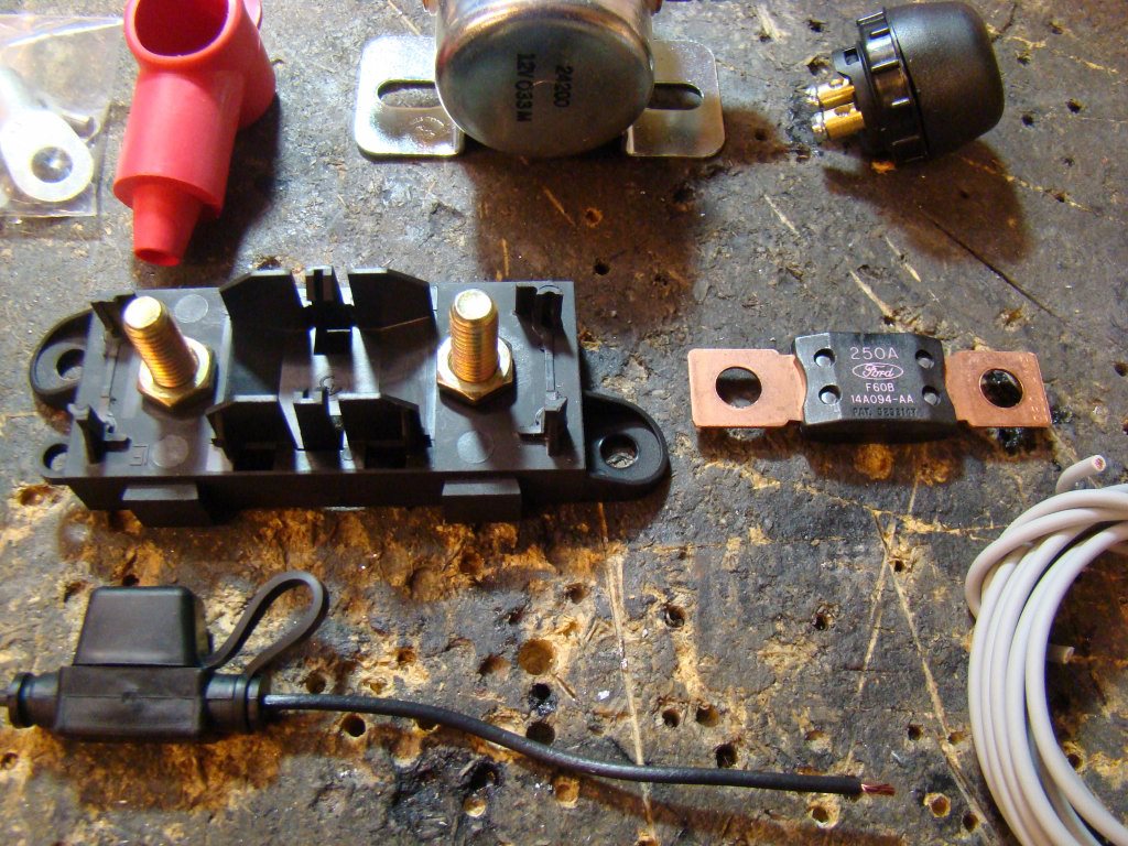
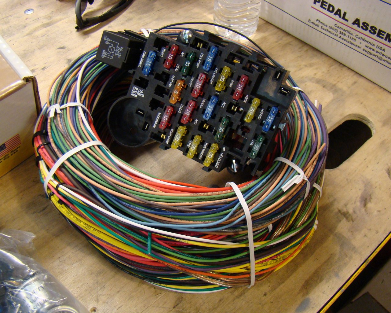
5/13/13 - I've discovered too much about the ISIS system (below) to prevent myself from investing in the system. The Painless wiring harness (below) will be removed and I will begin the installation of the ISIS Multiplexing system soon. (Its in the mail). I'll be going with the 3 cell system with the In Touch electric reversing system, Vintage air interface for the A/C and heating, remote control, Kenwood 990 WIFI/Blue tooth head unit w/7" touch screen (above), reverse camera etc...etc. There's simply too many options that work with the ISIS system to walk away at this point. Now, all of it can be controlled via the Kenwood touchscreen and remote key fab. So, what you see below will be removed. Glad I didn't do more with the wiring!
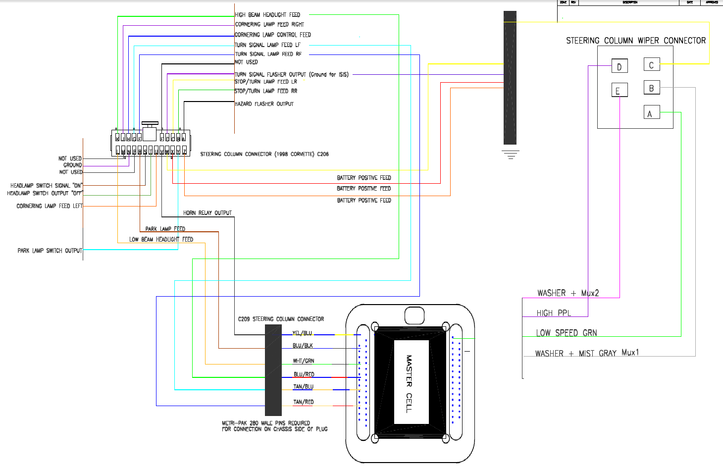
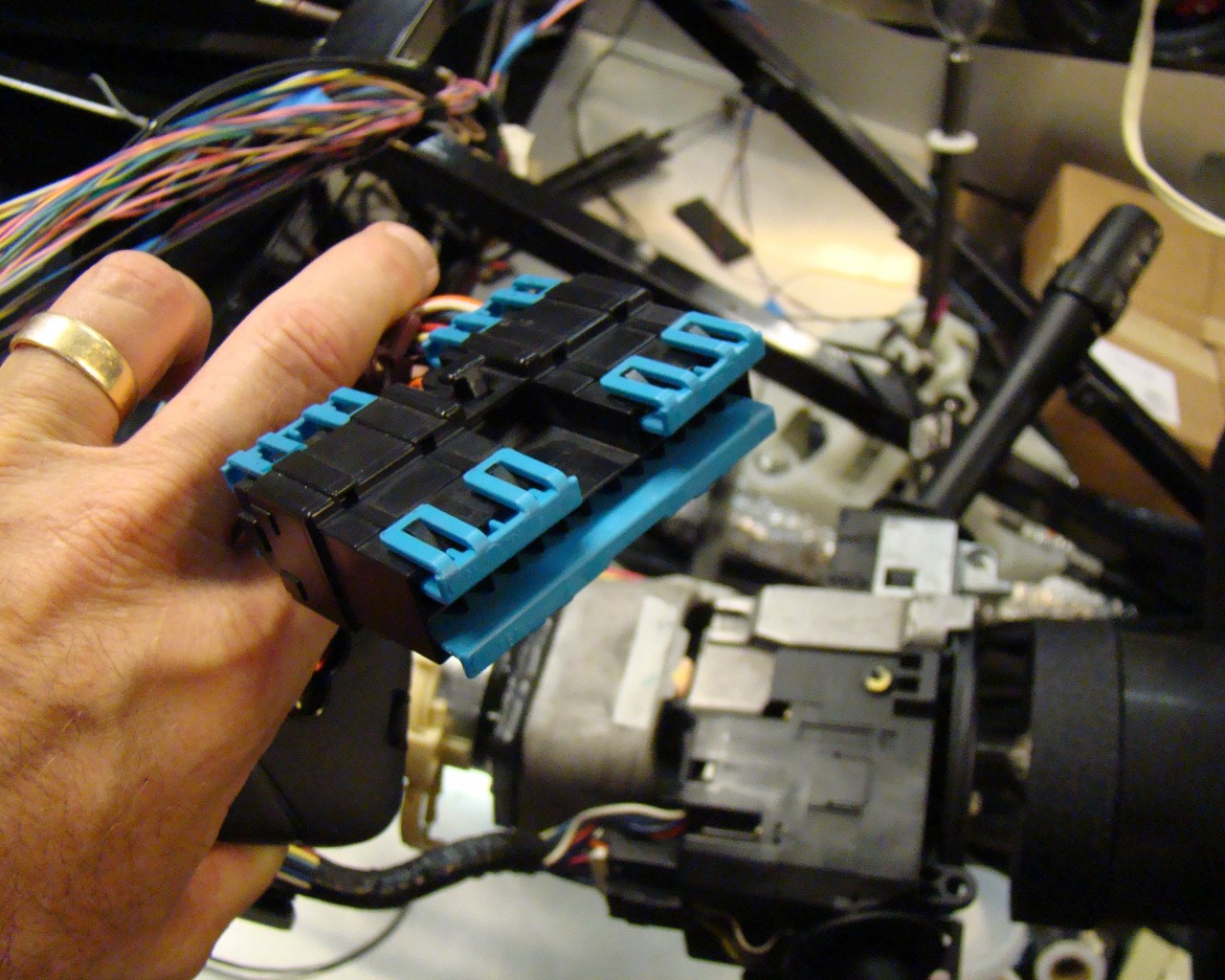
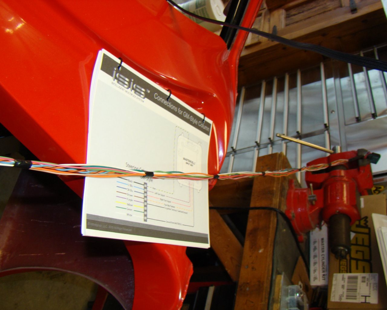
C5 STEERING COLUMN CONNECTIONS TO ISIS:
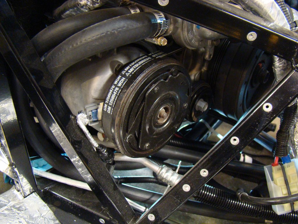
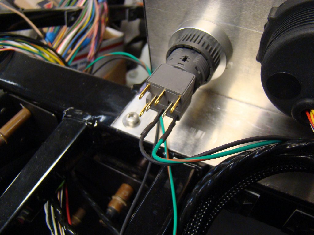
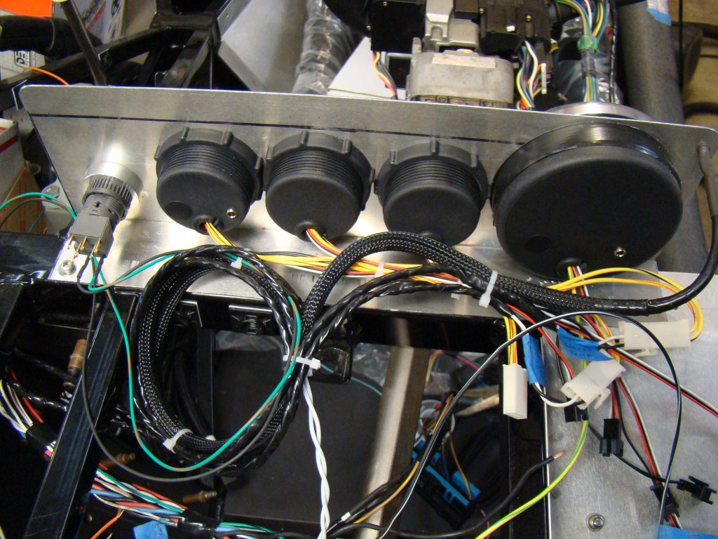
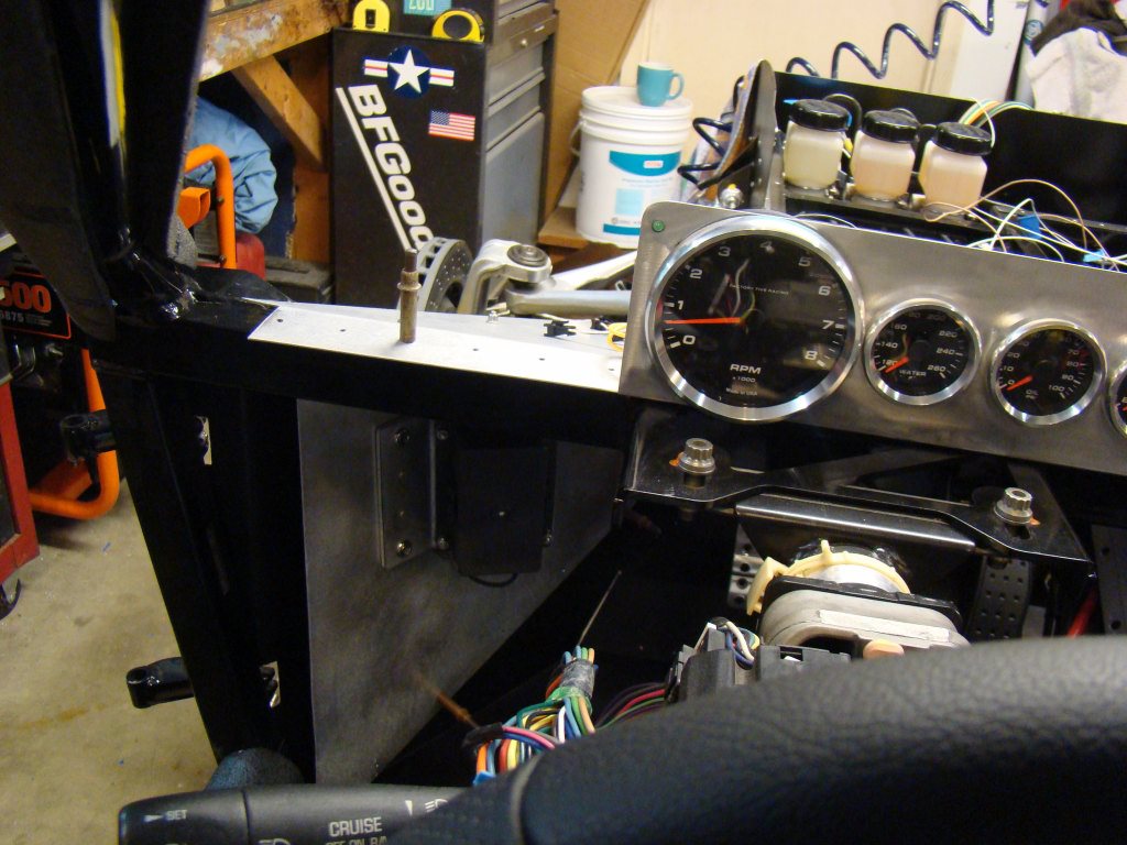
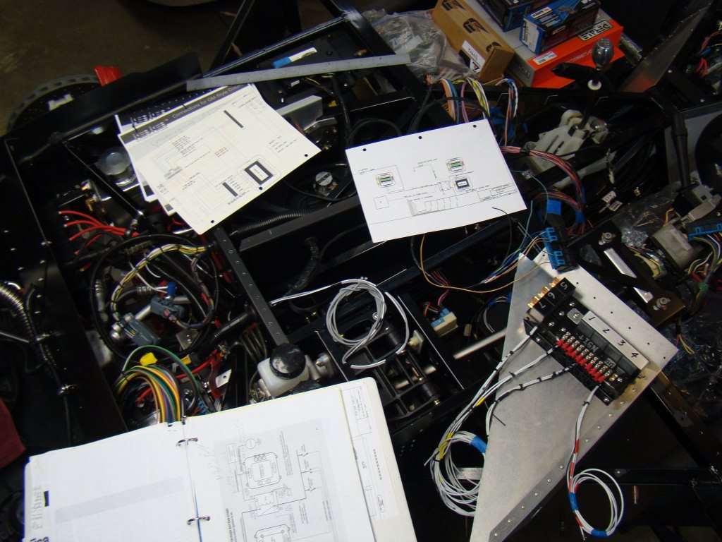
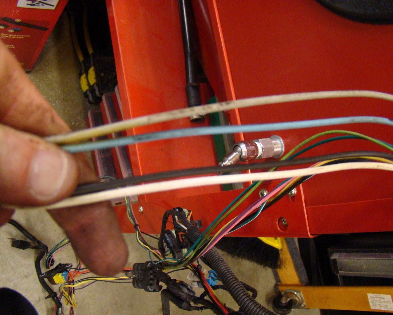
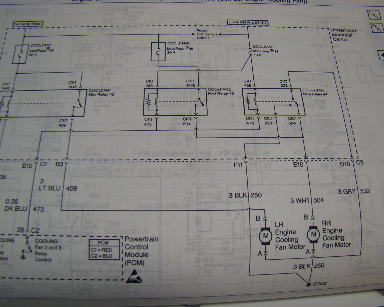
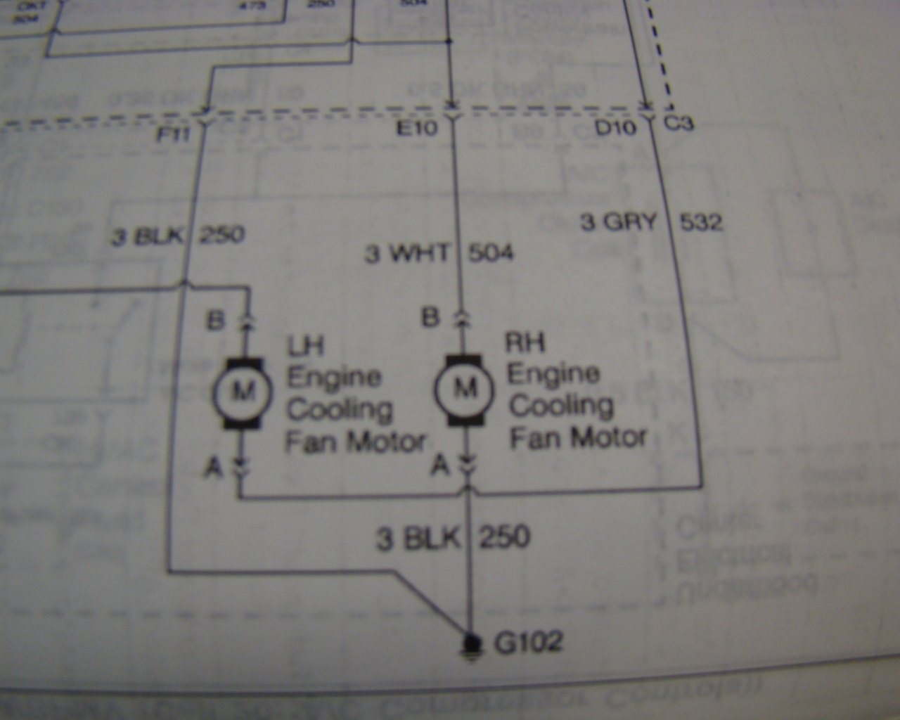
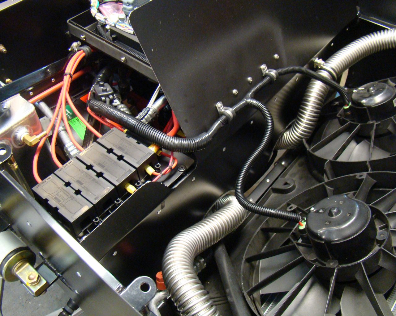
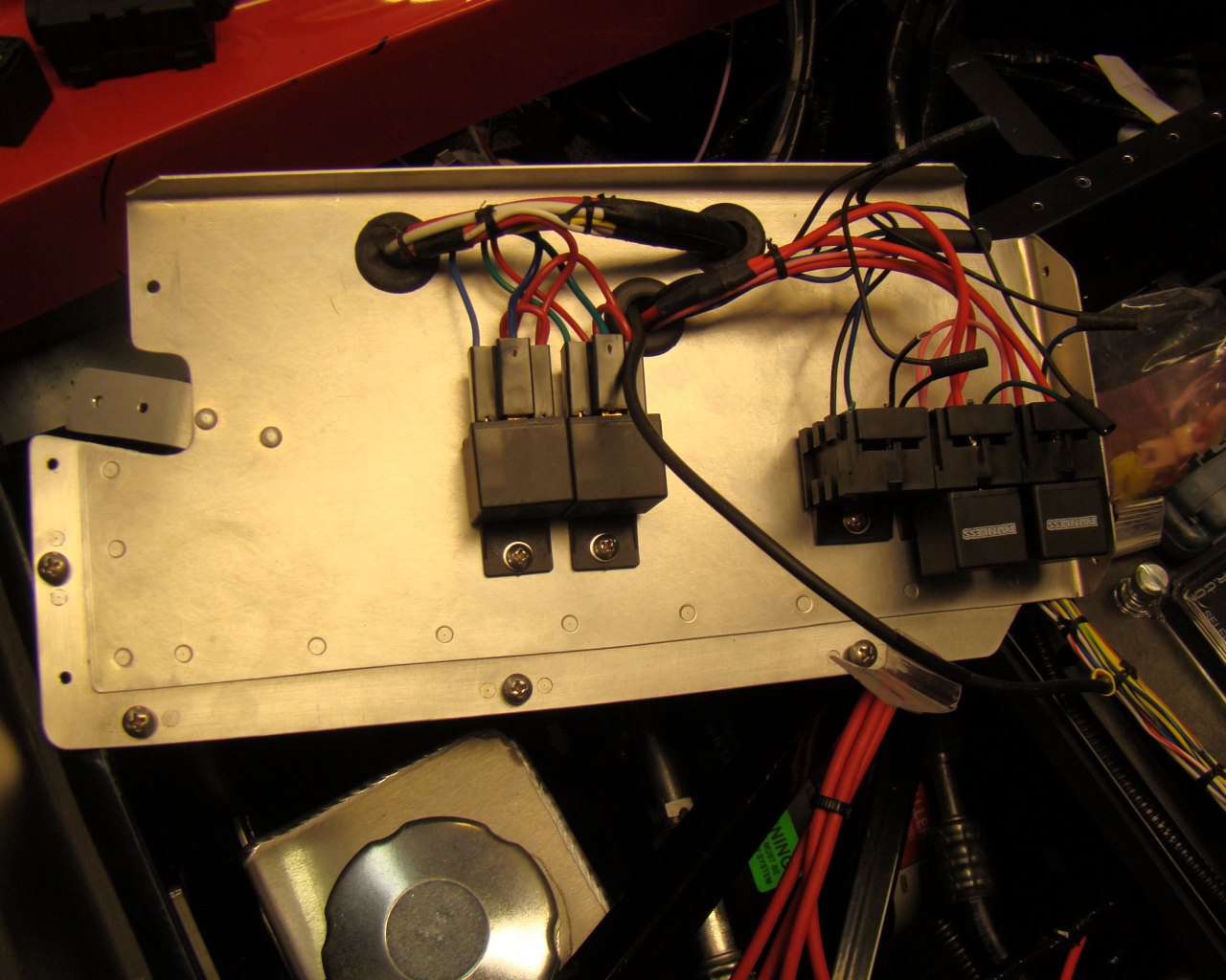
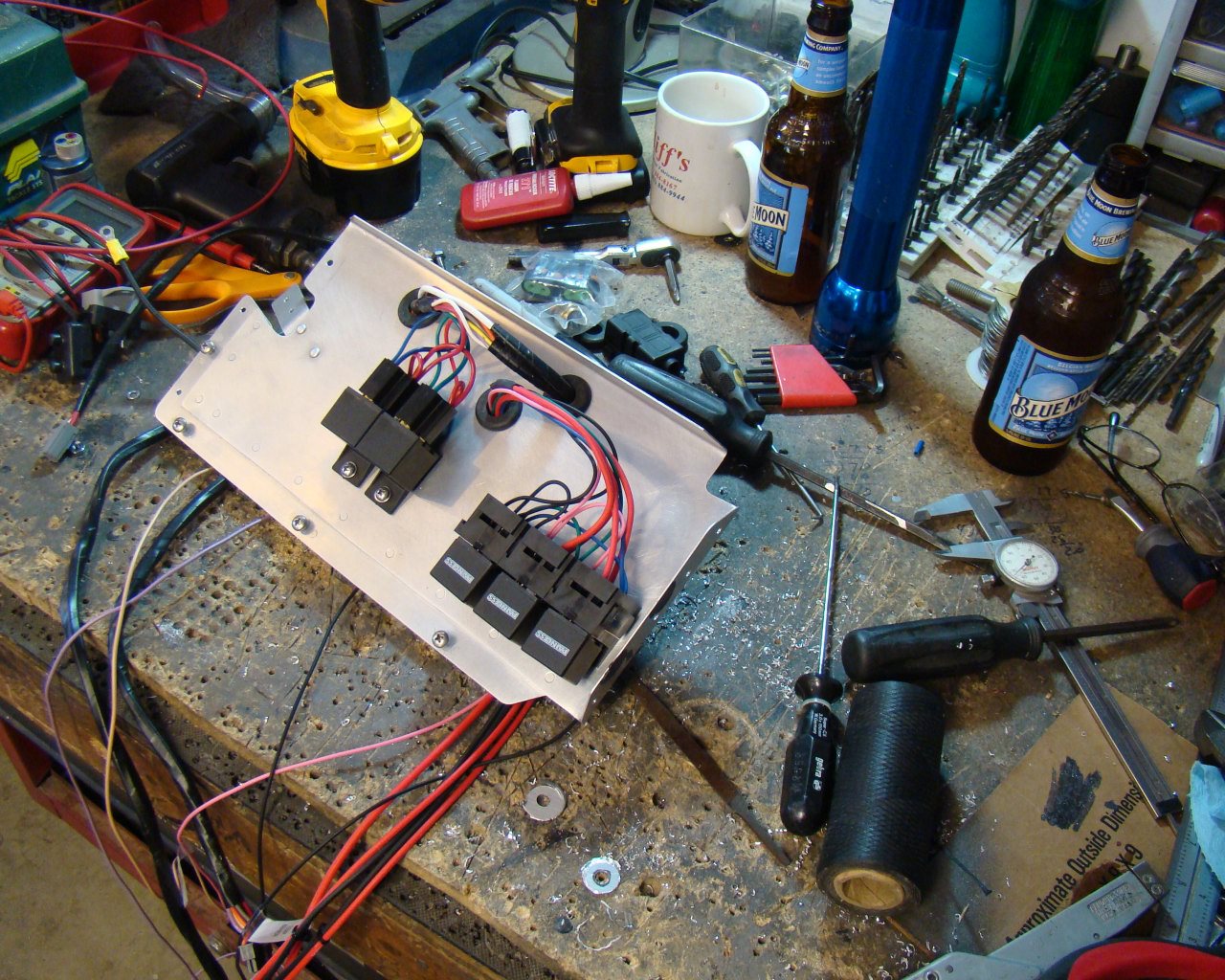
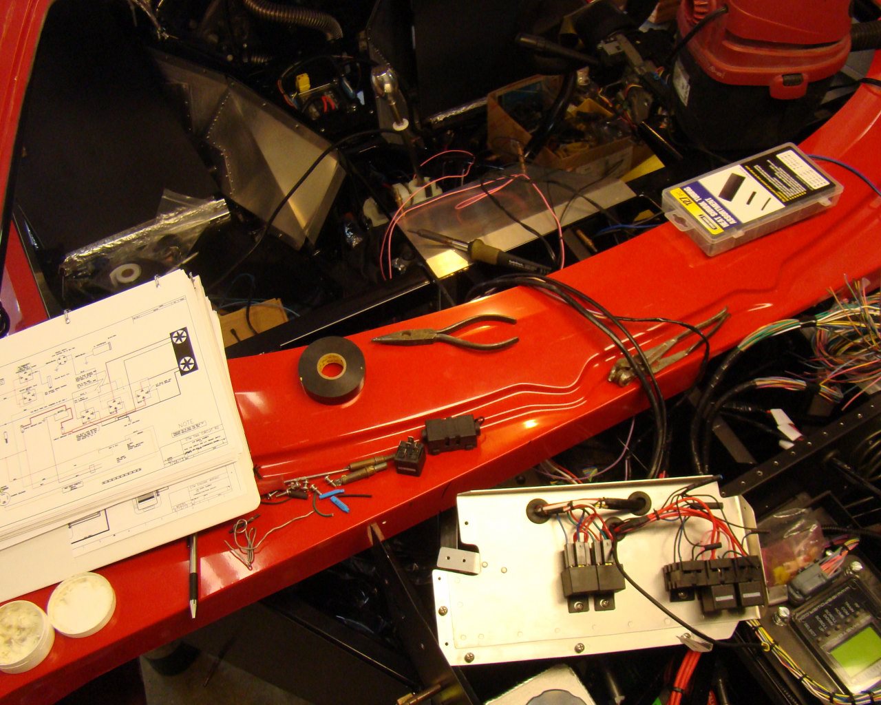
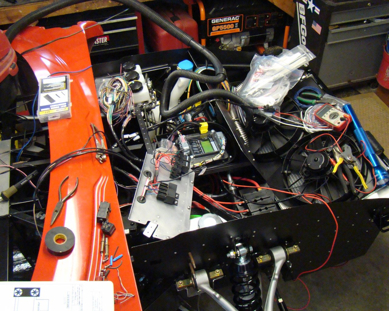
DUAL FANS: The below schematic/diagram shows how I wired the fans. I tested the circuits and assuming all feeds from the compressor, ECU, Trinary switch etc. will in fact feed 12V to the relays, the system will work. I actually applied the 12 volts to each relay signal wire and the fans worked. The relays work as shown. THE MIDDLE RELAY IS MISSING THE GROUND WIRE BECAUSE I FORGOT IT IN THE DRAWING so make sure you ground it. I just added it with pencil for my own record.

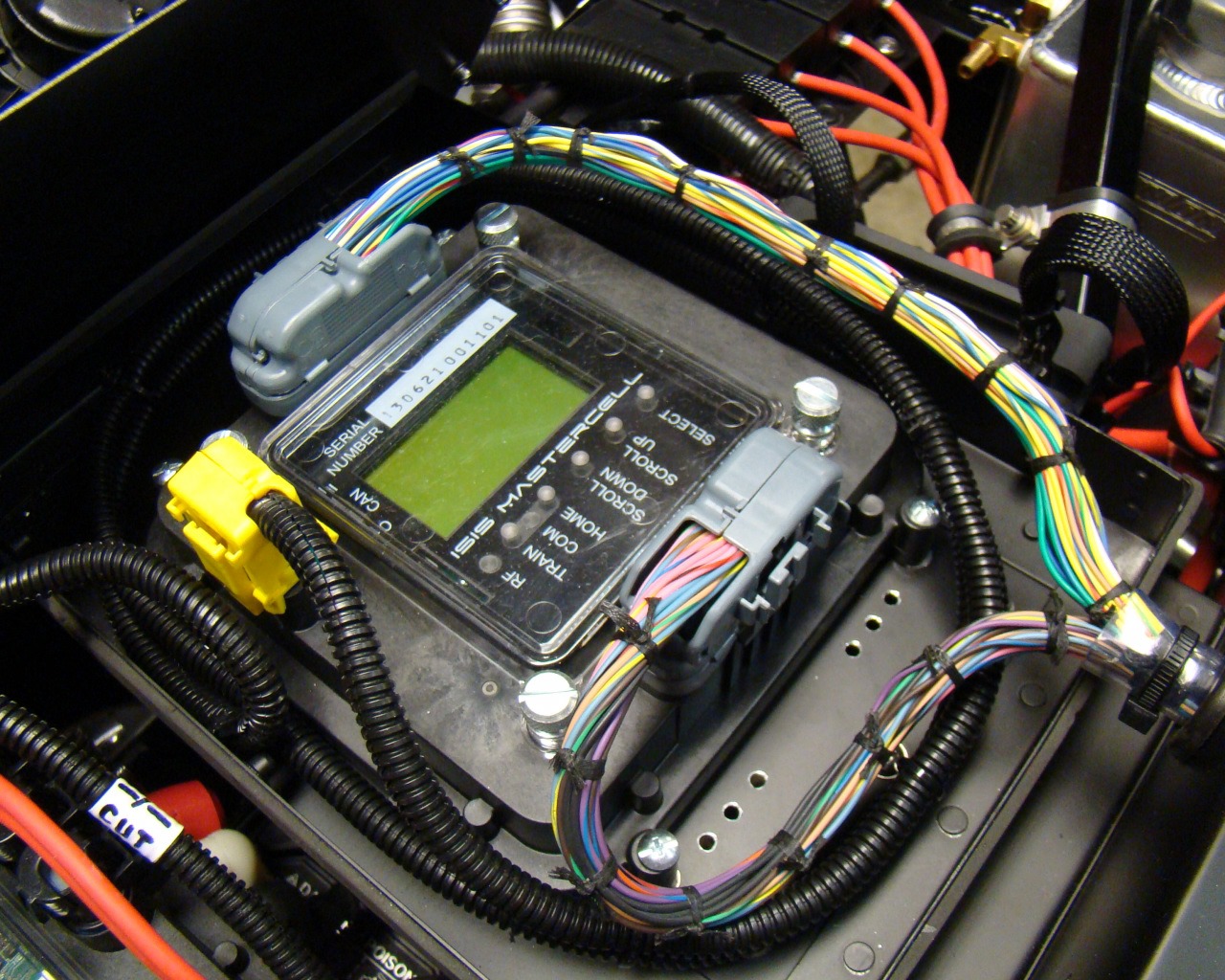
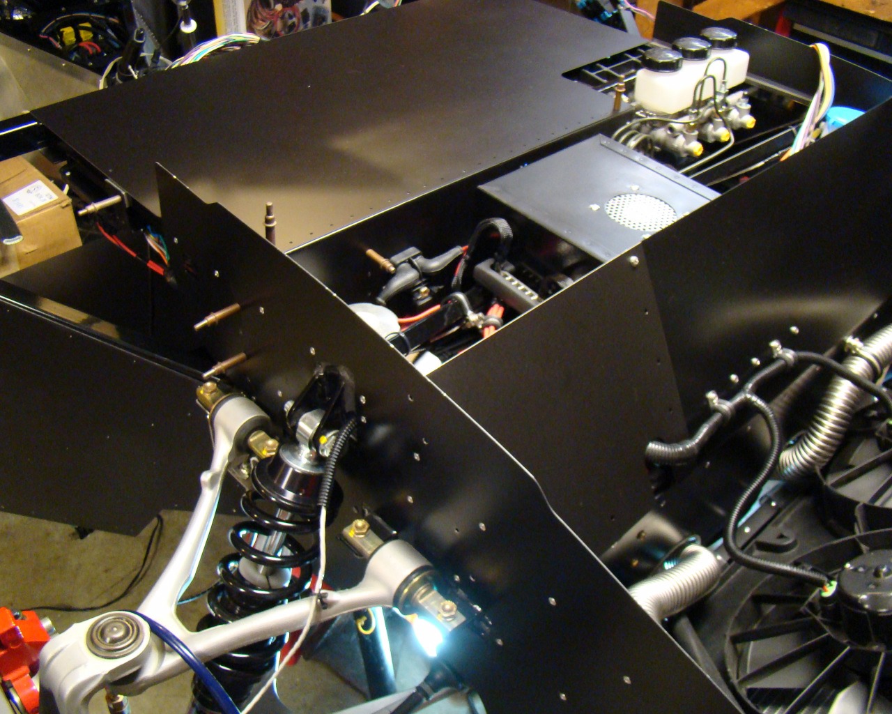
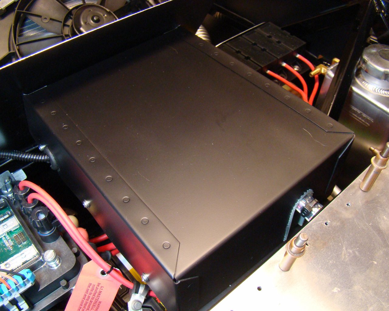
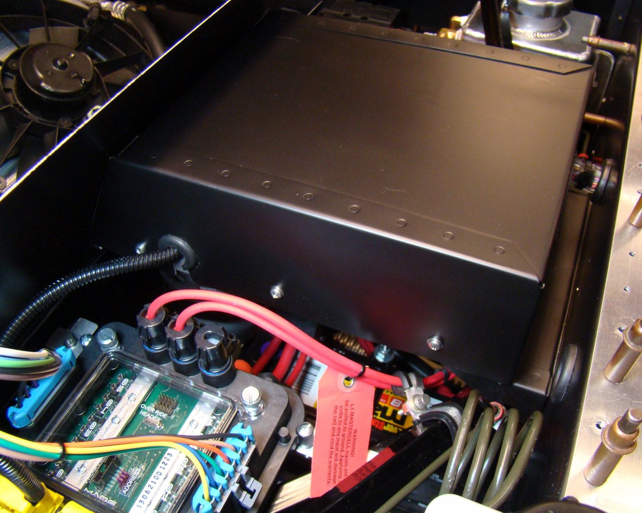
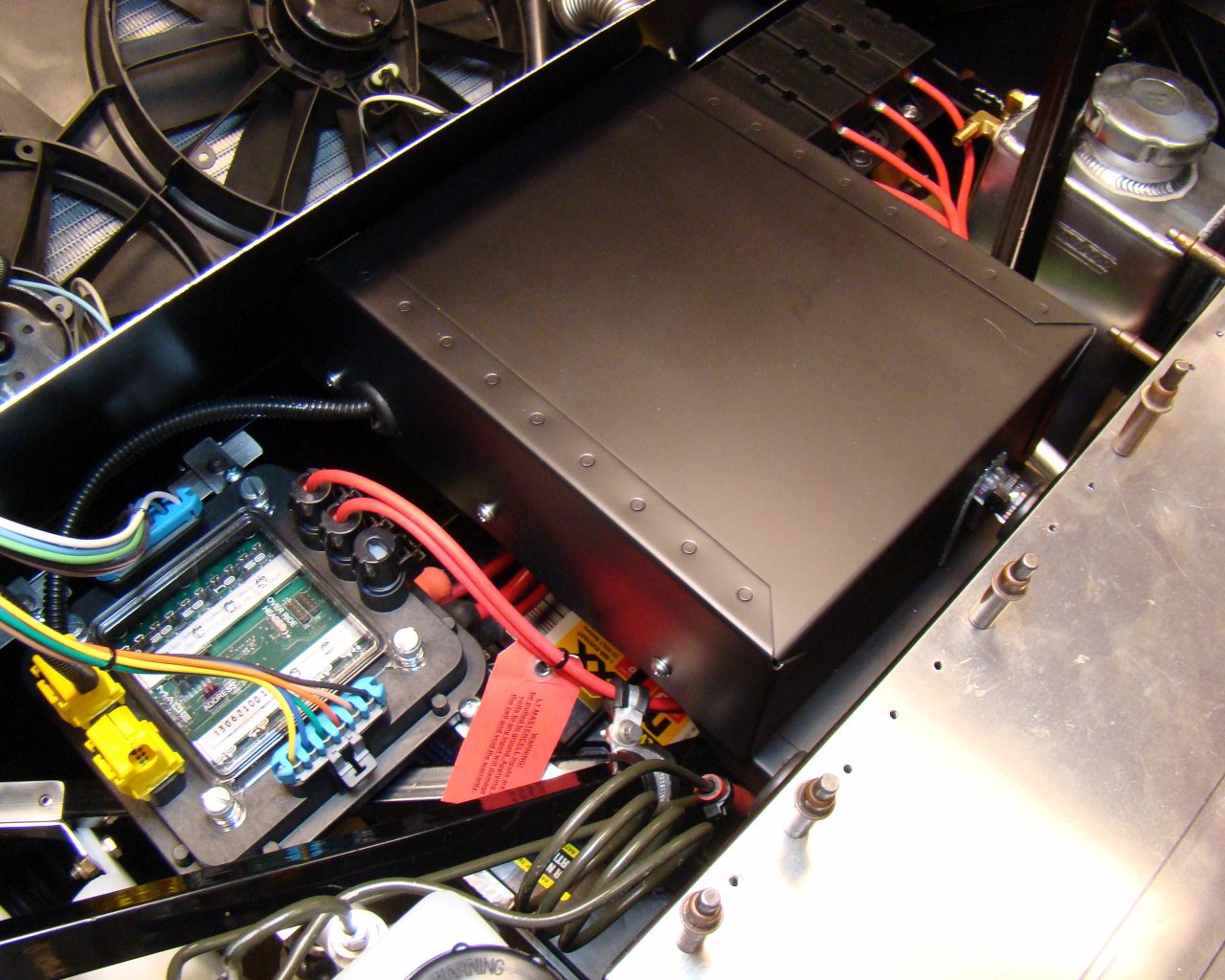
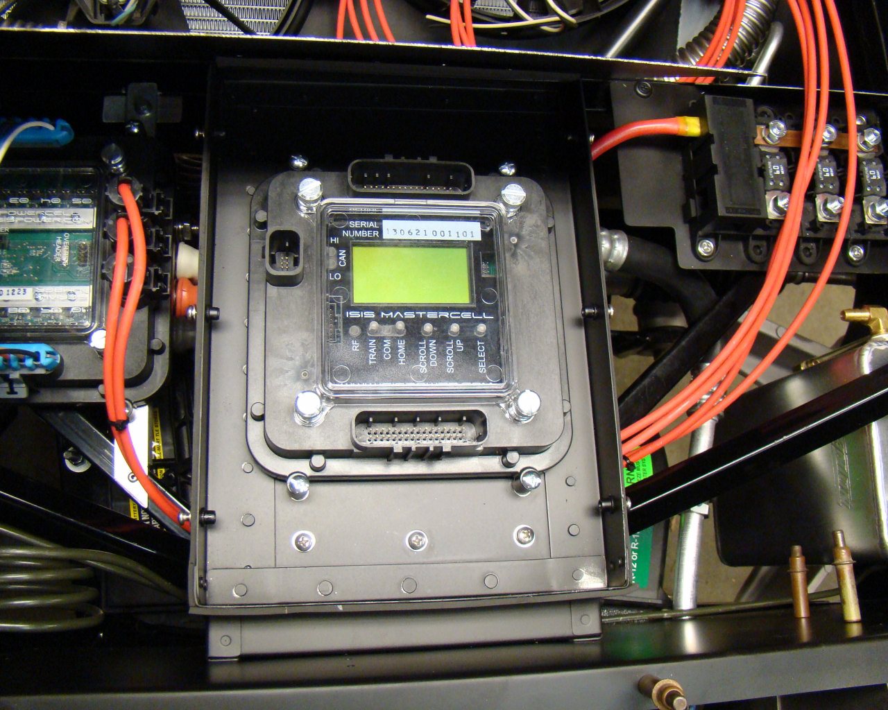
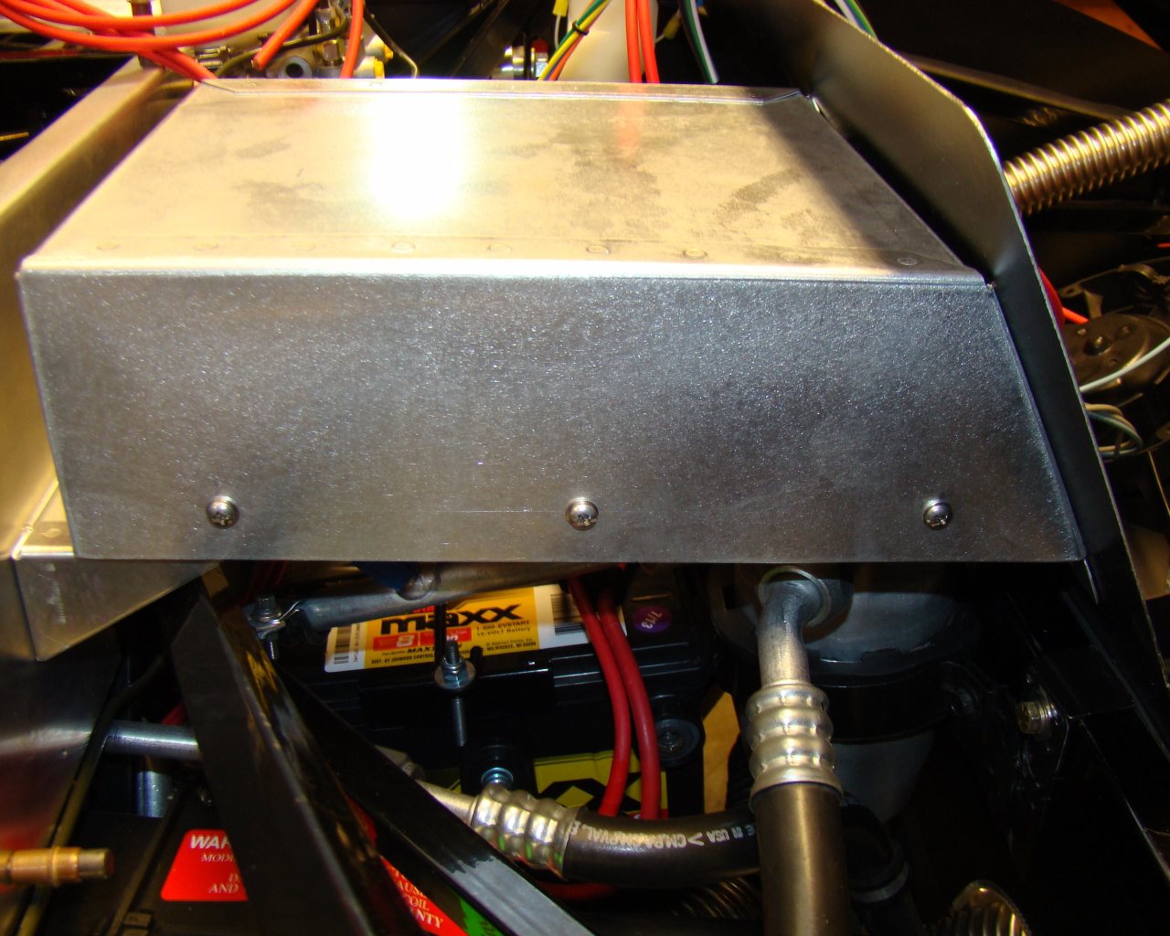
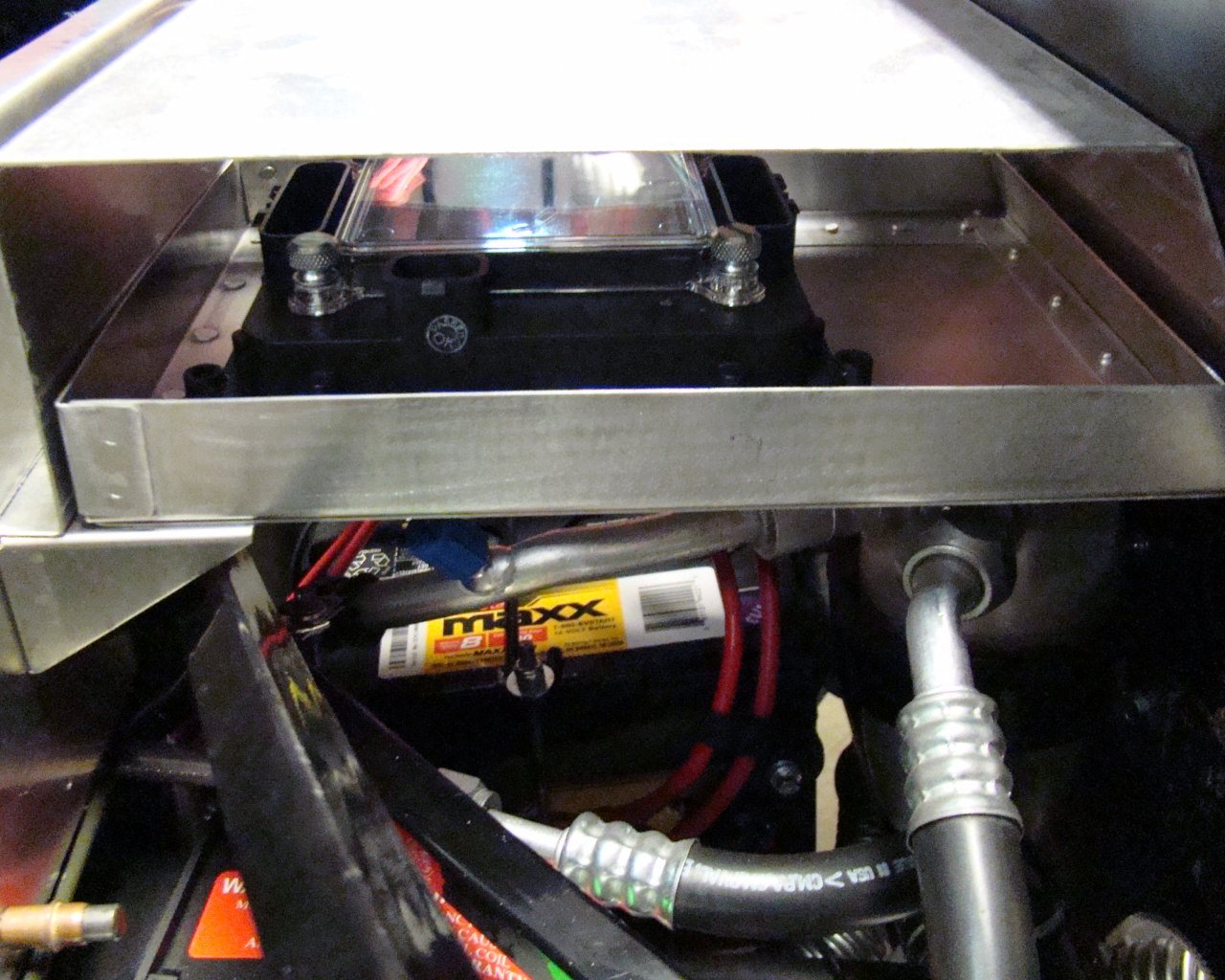
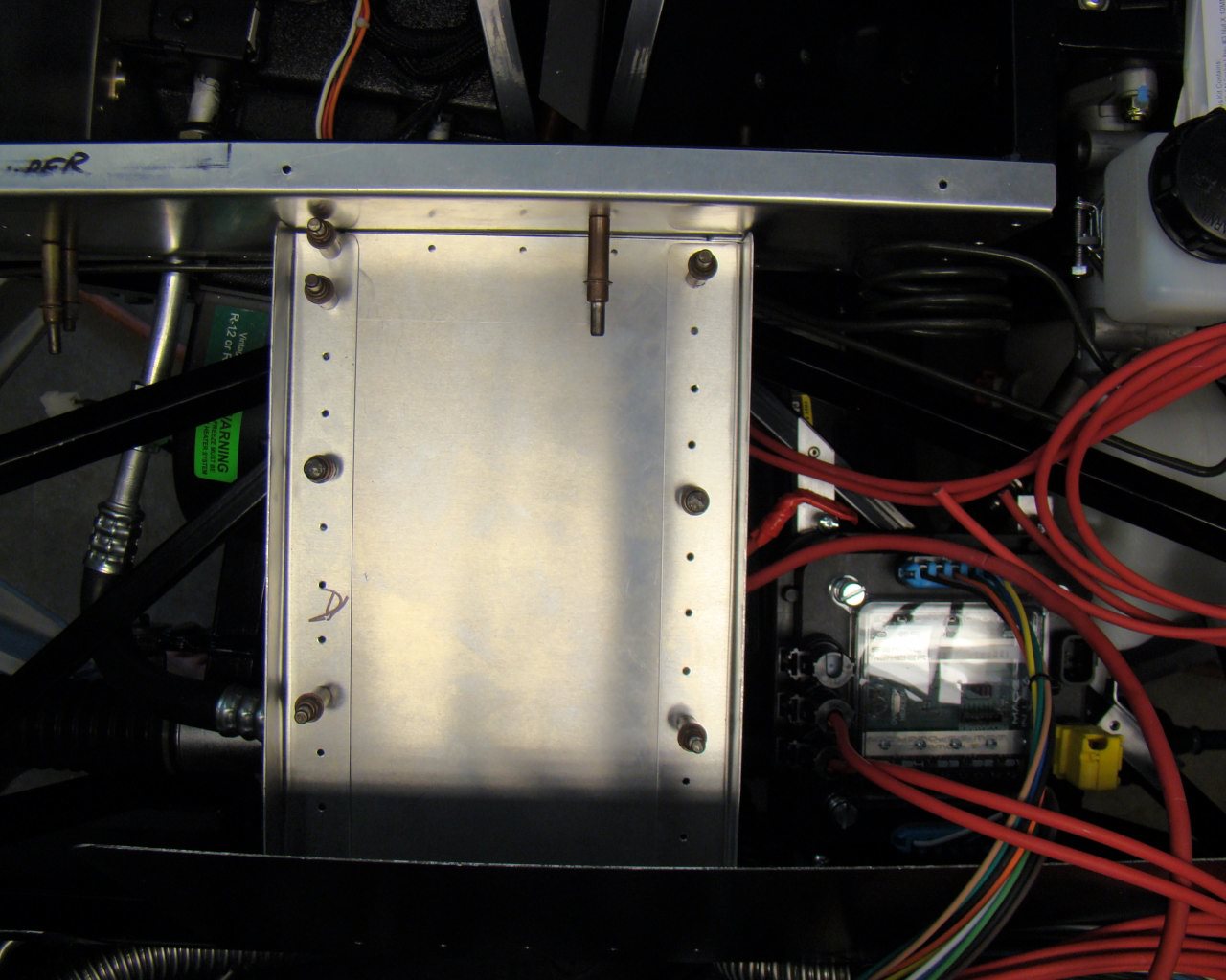
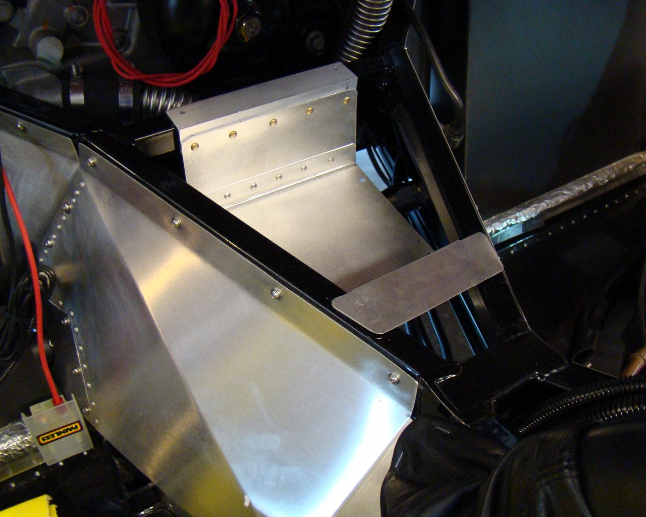
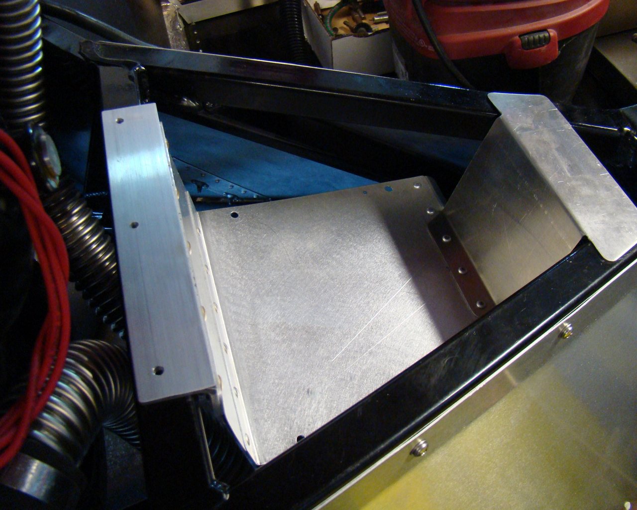
Note cooling holes in the floor of the Master Cell cover.
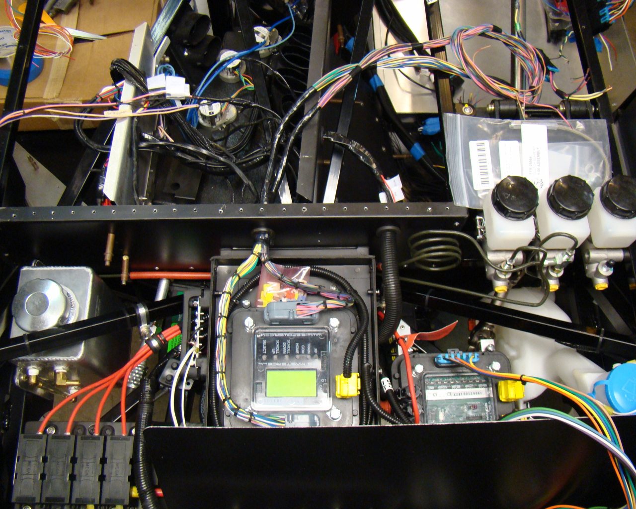
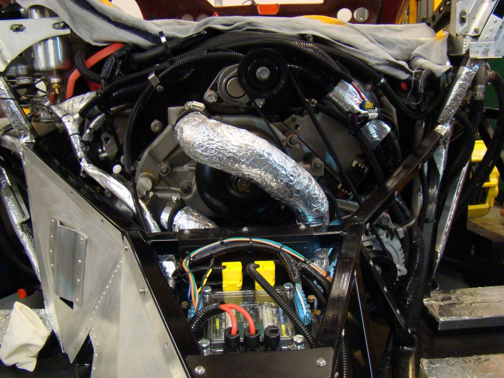
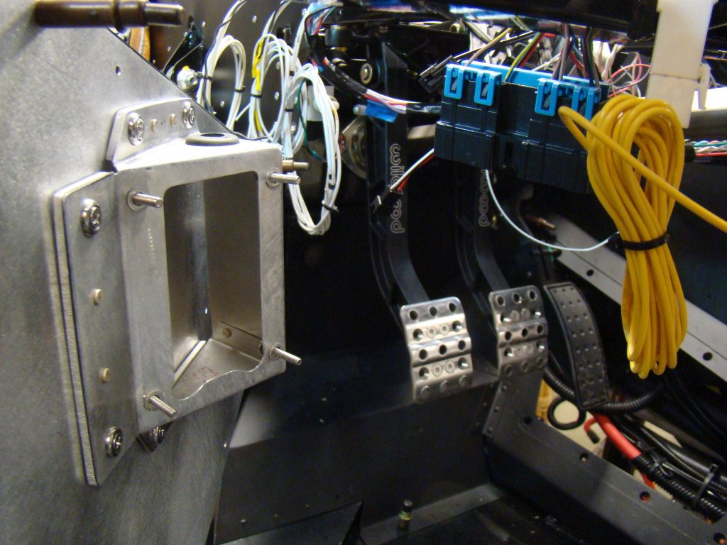
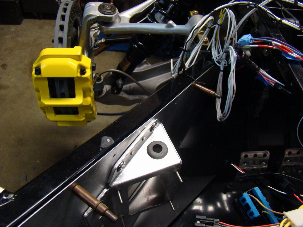
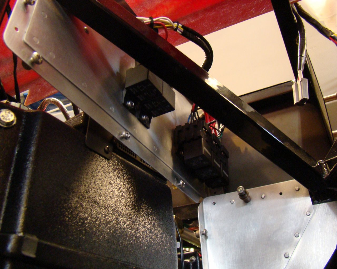
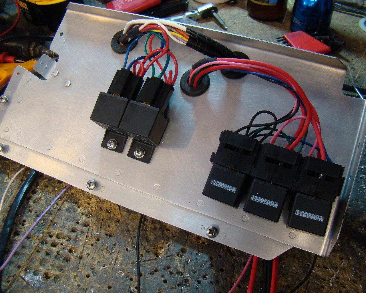
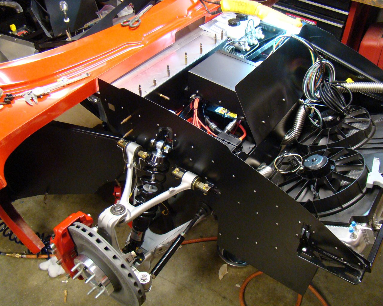
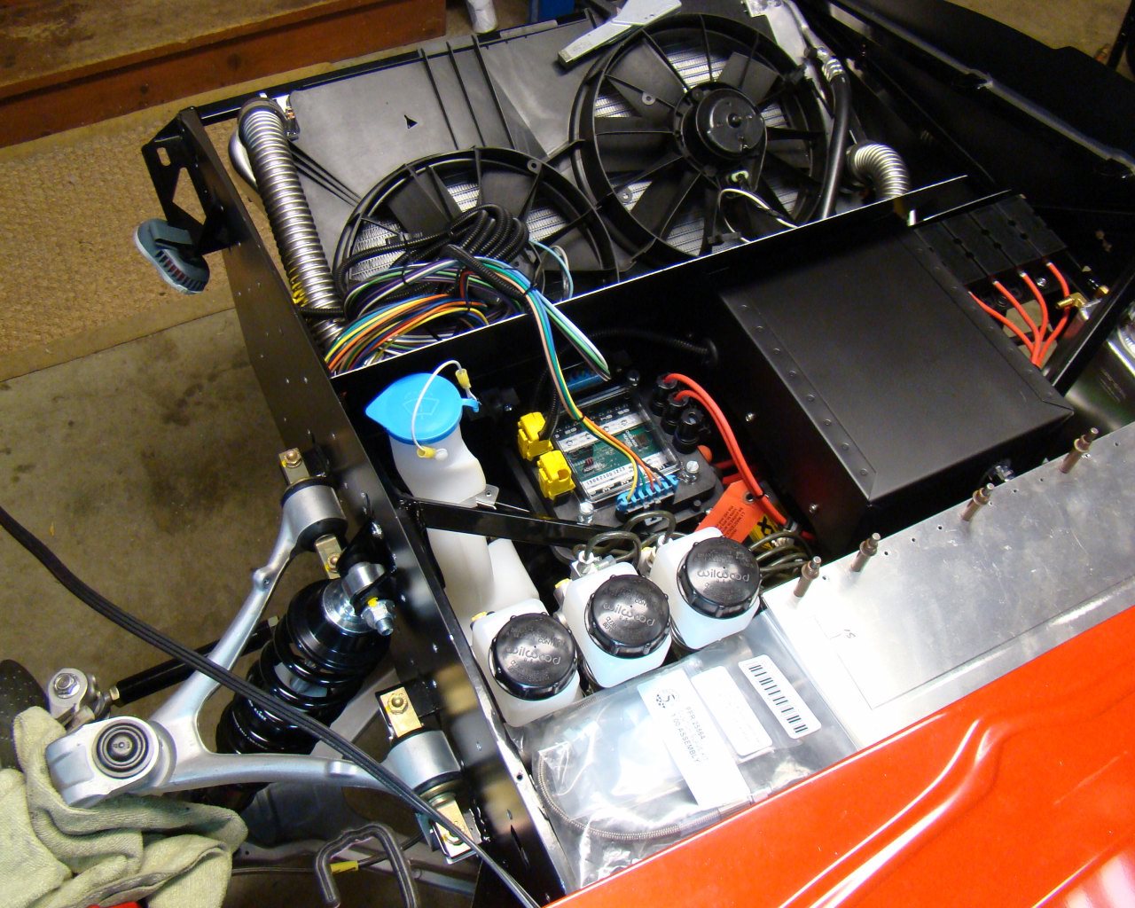
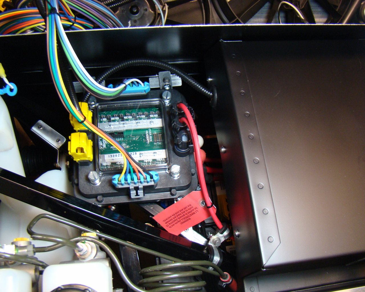
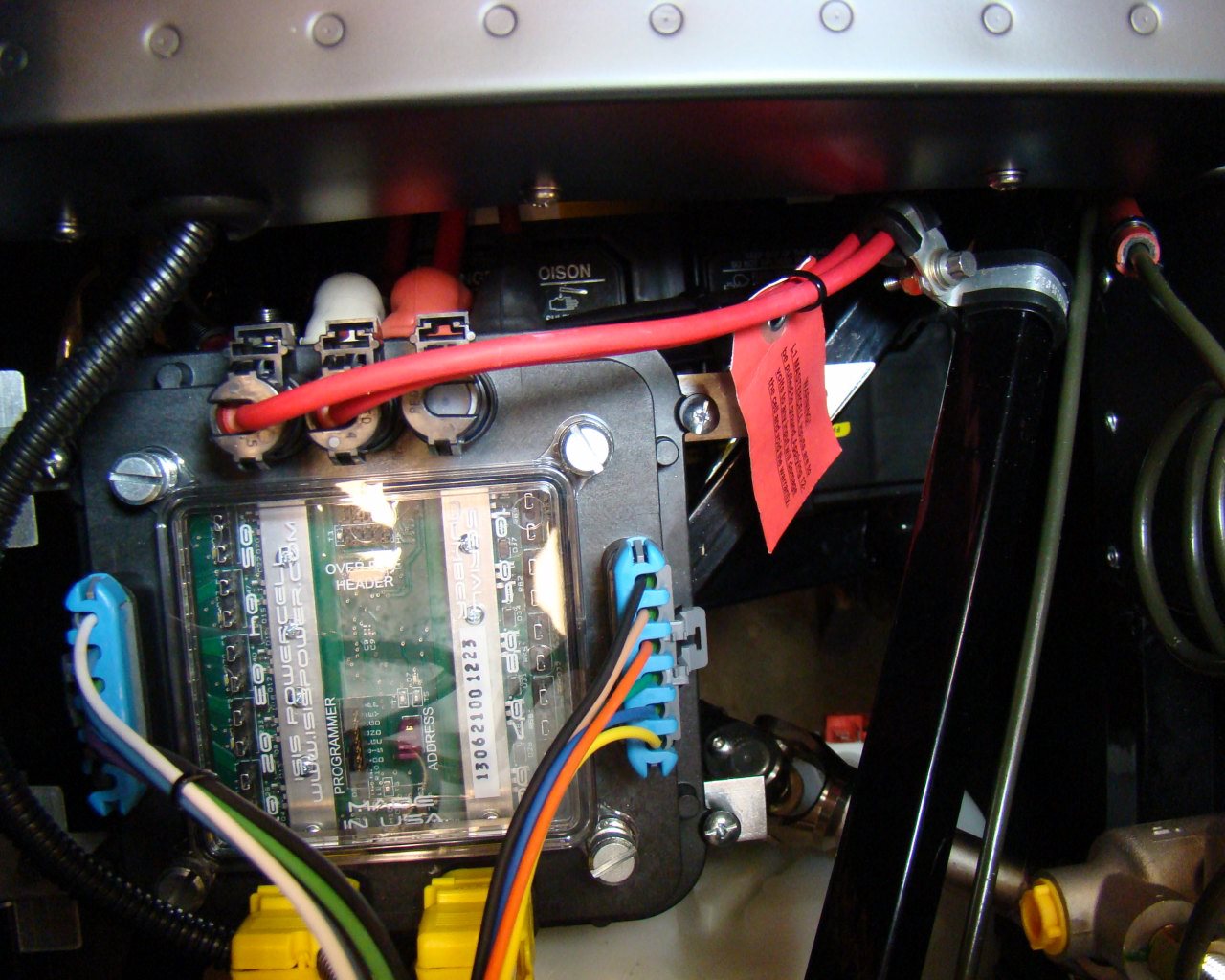
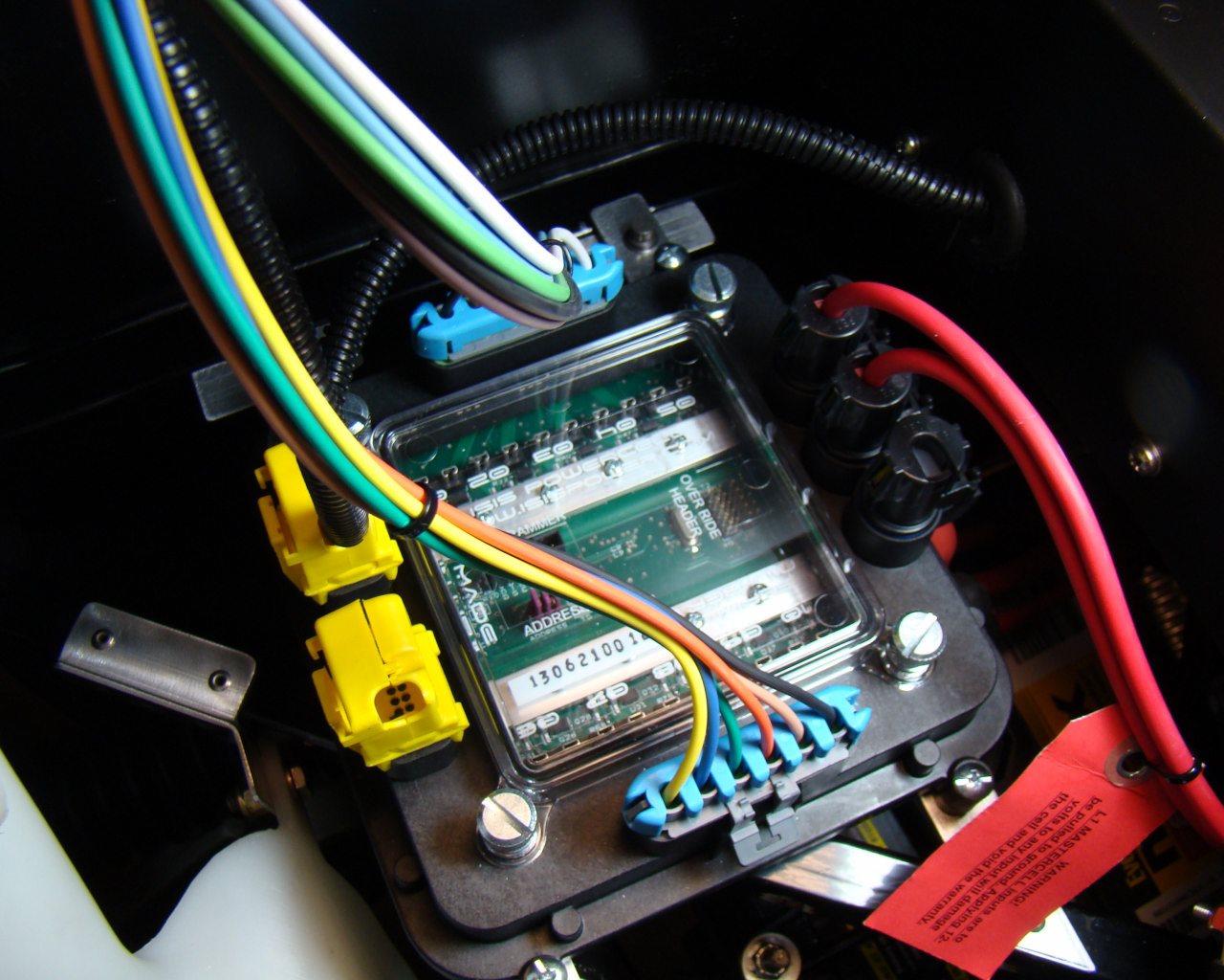
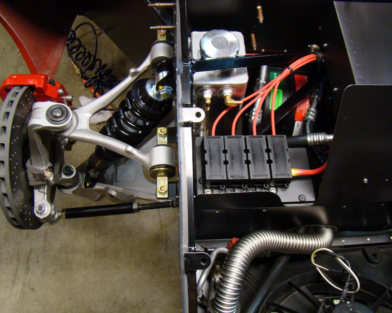
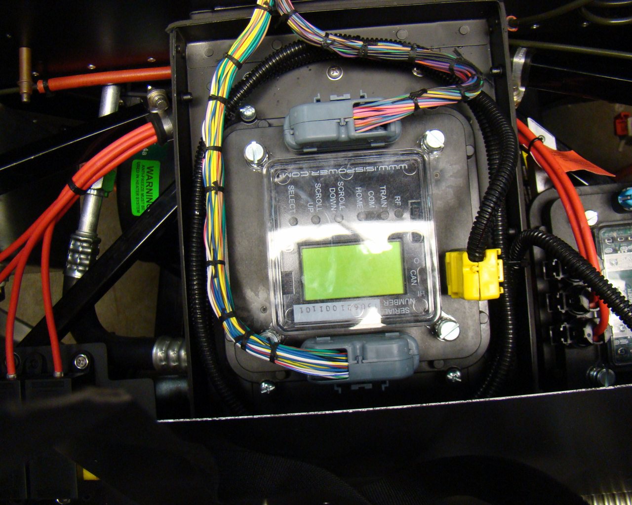
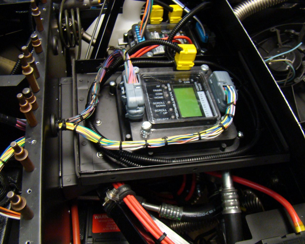
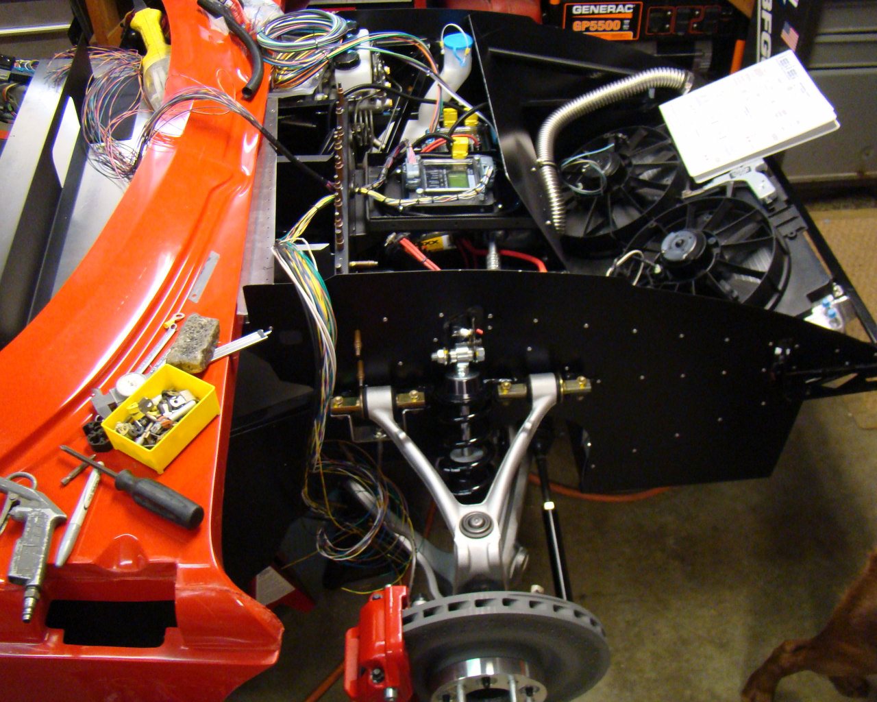
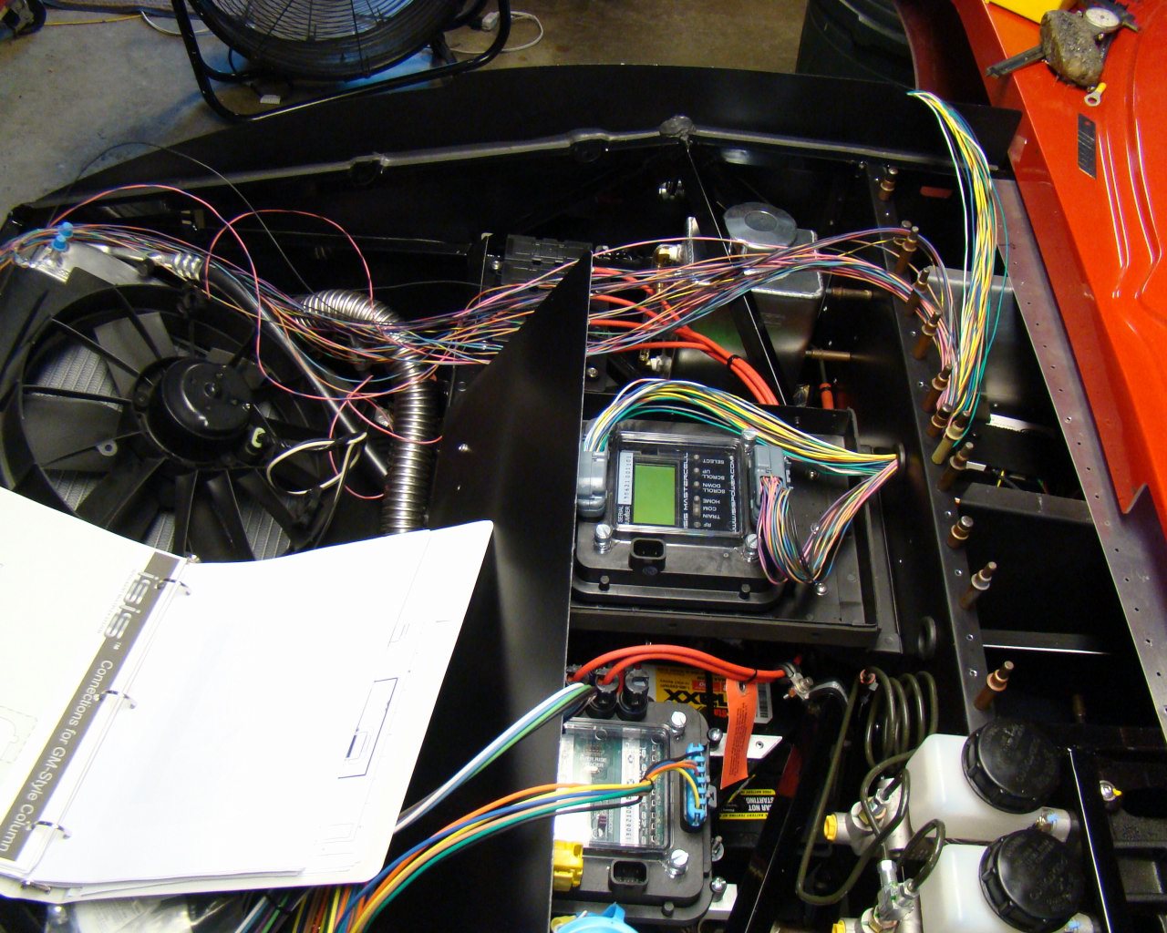
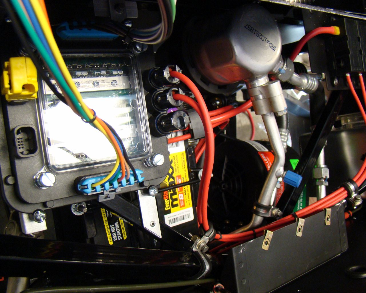
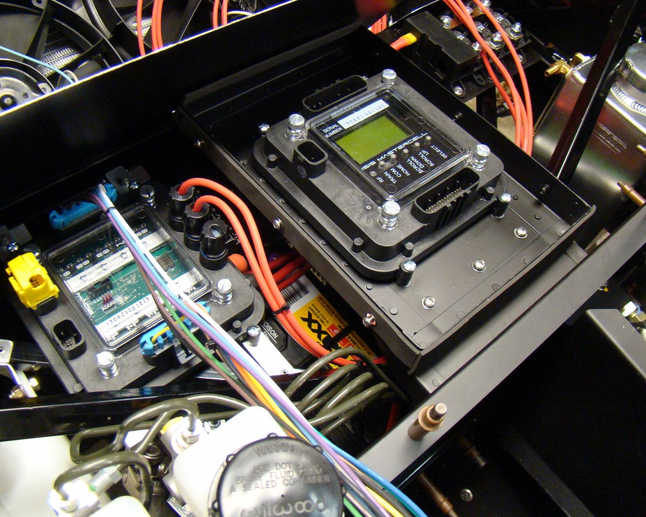
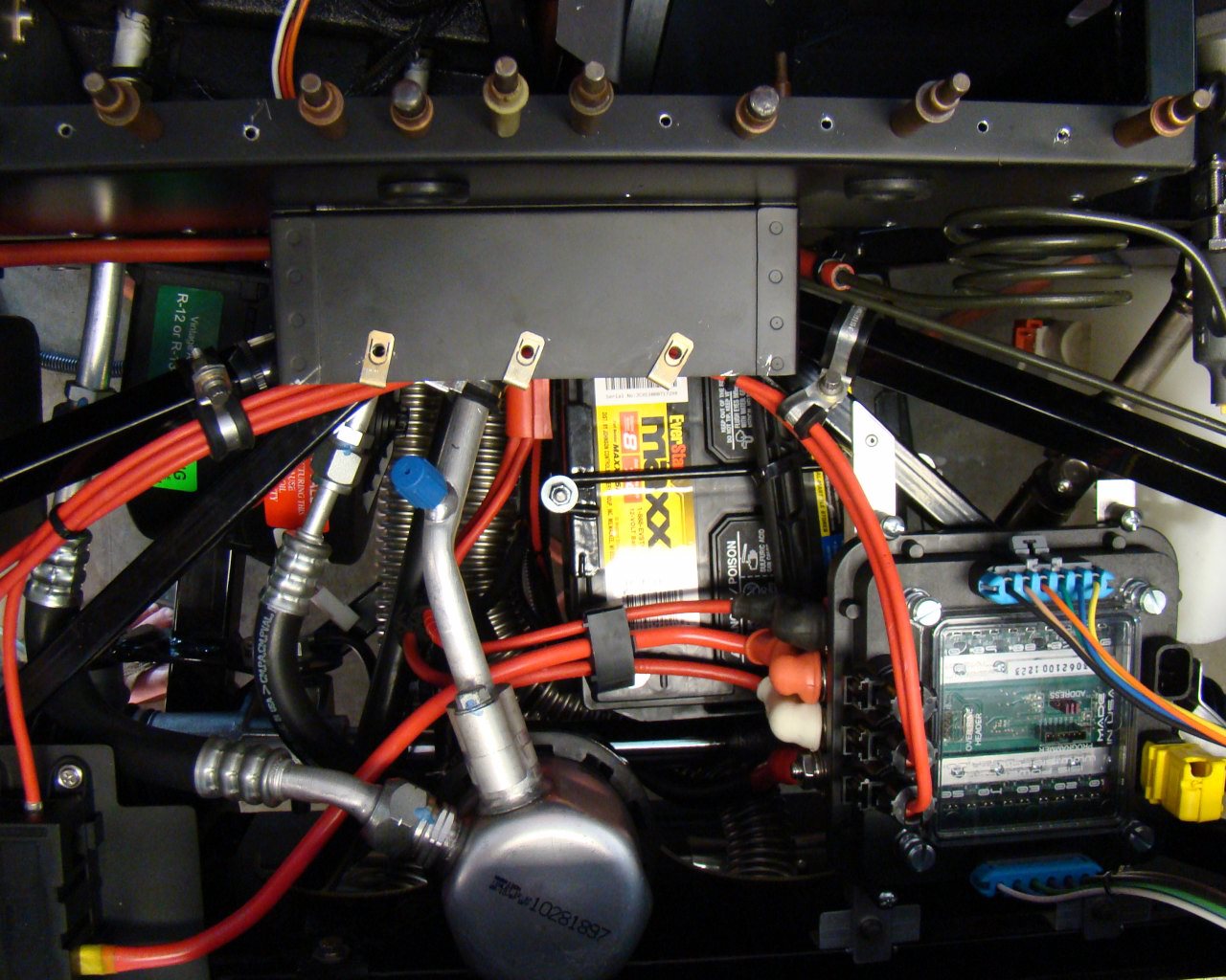
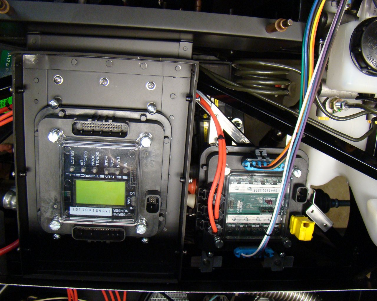
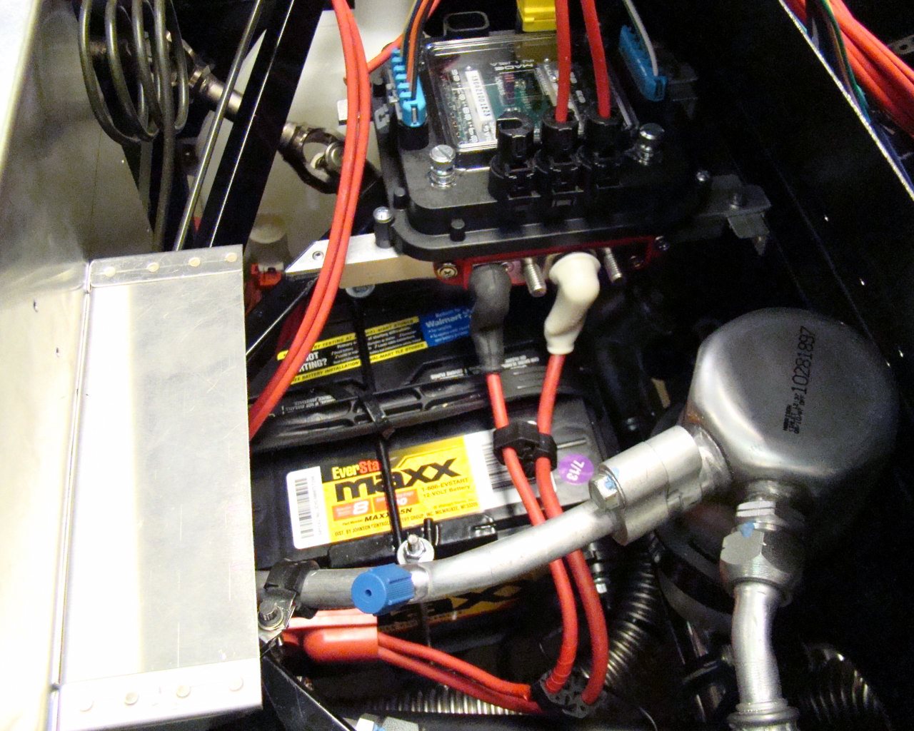
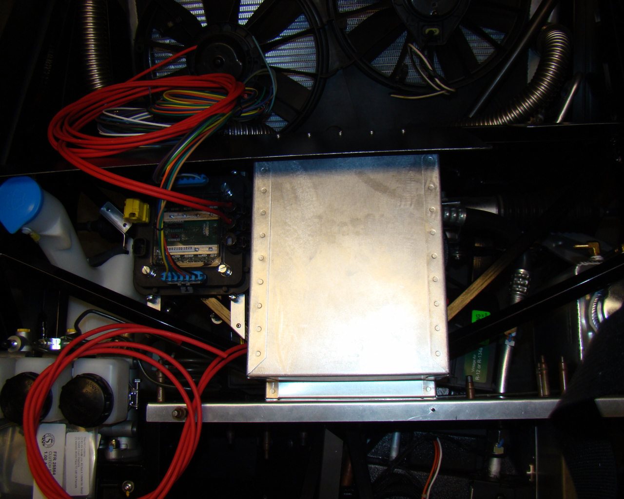
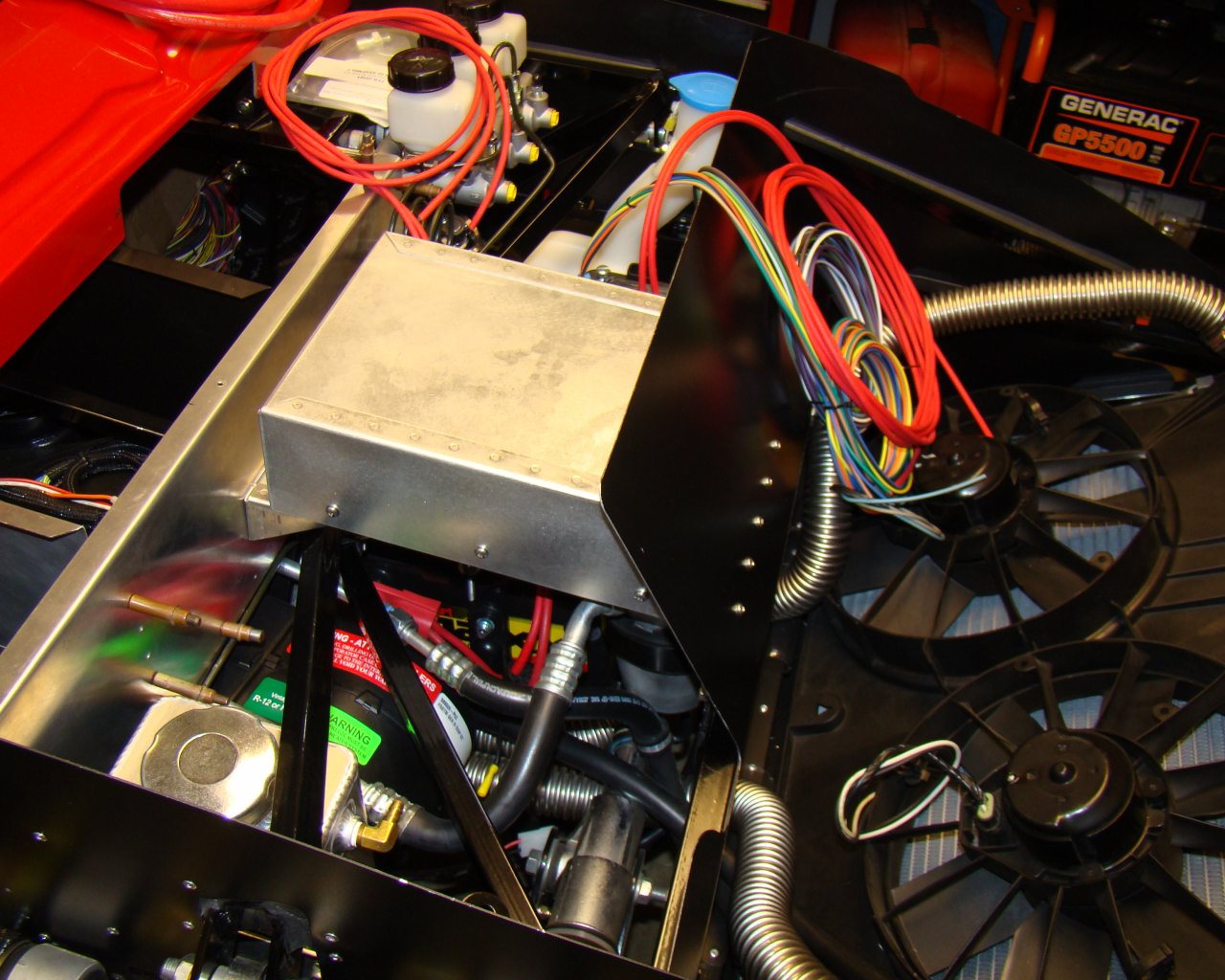
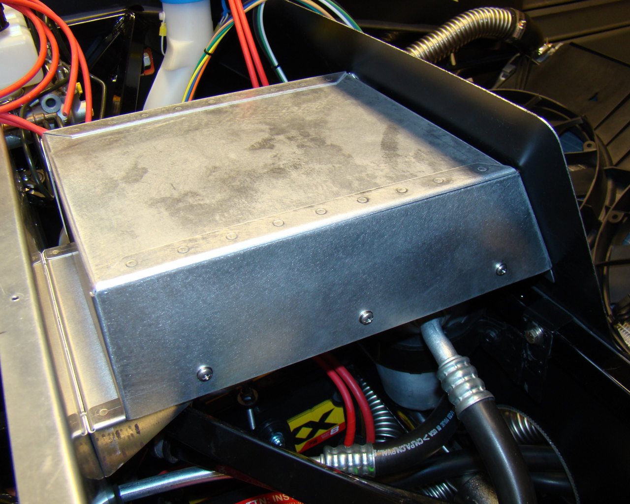
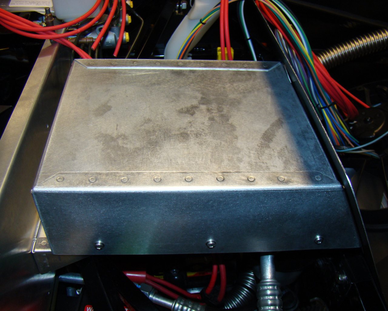
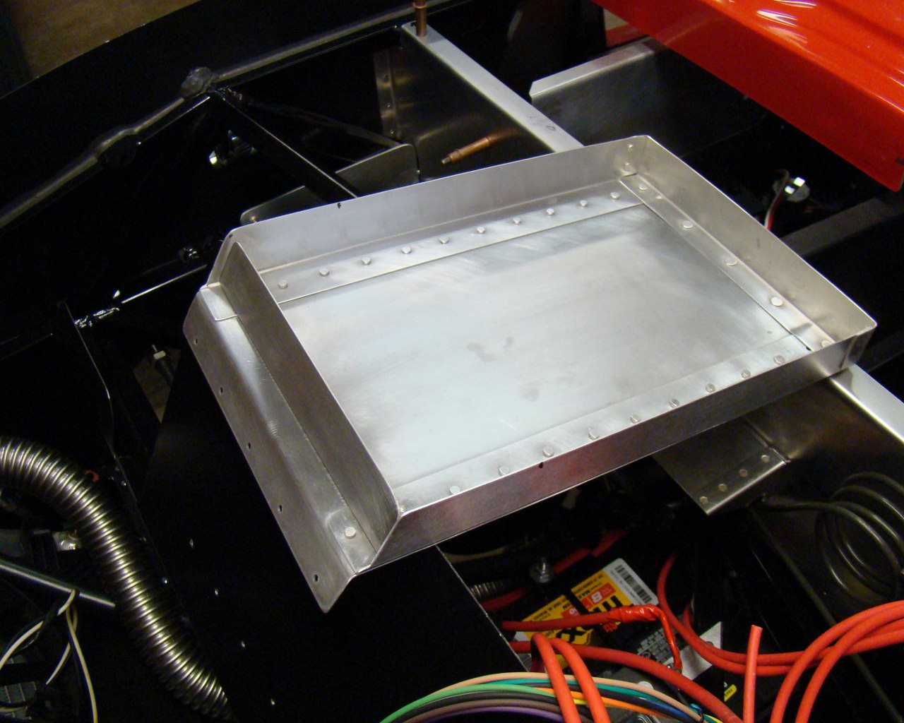
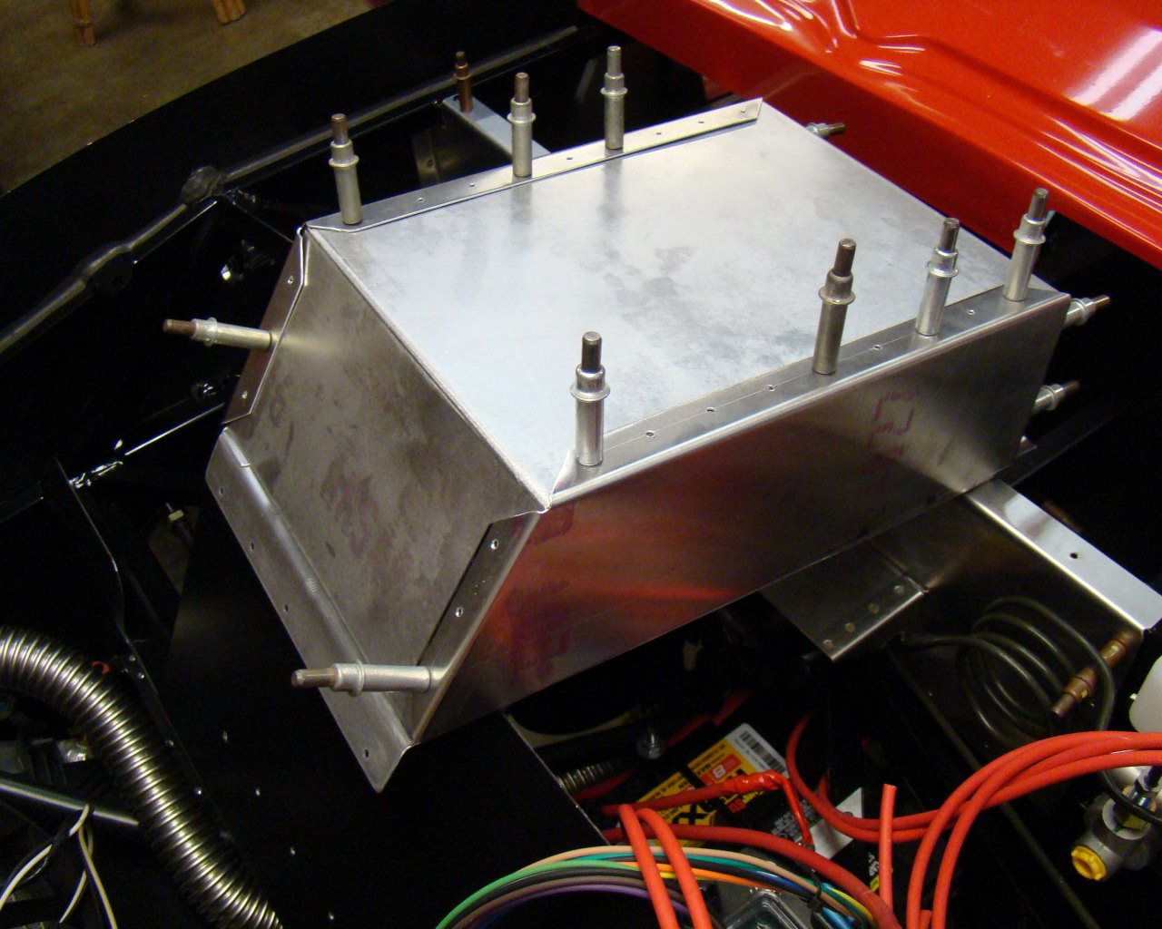
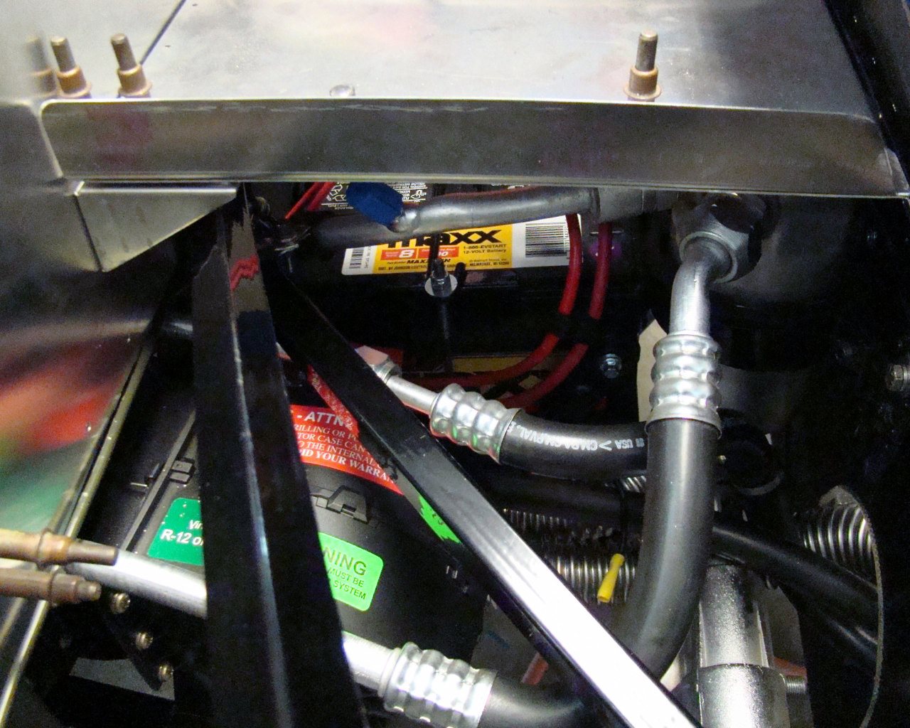
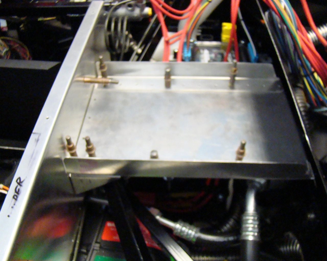
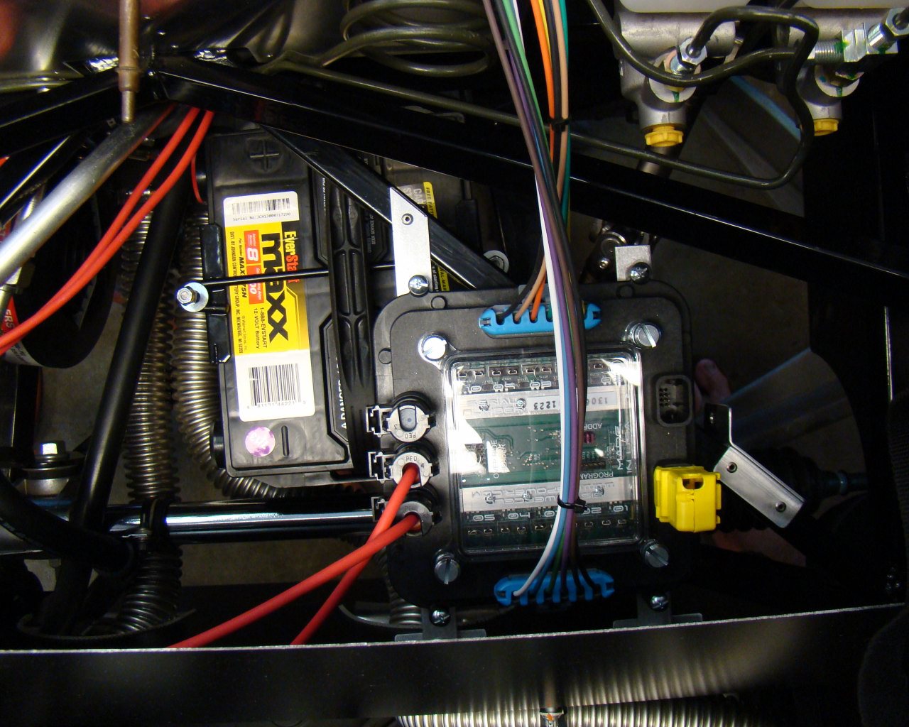
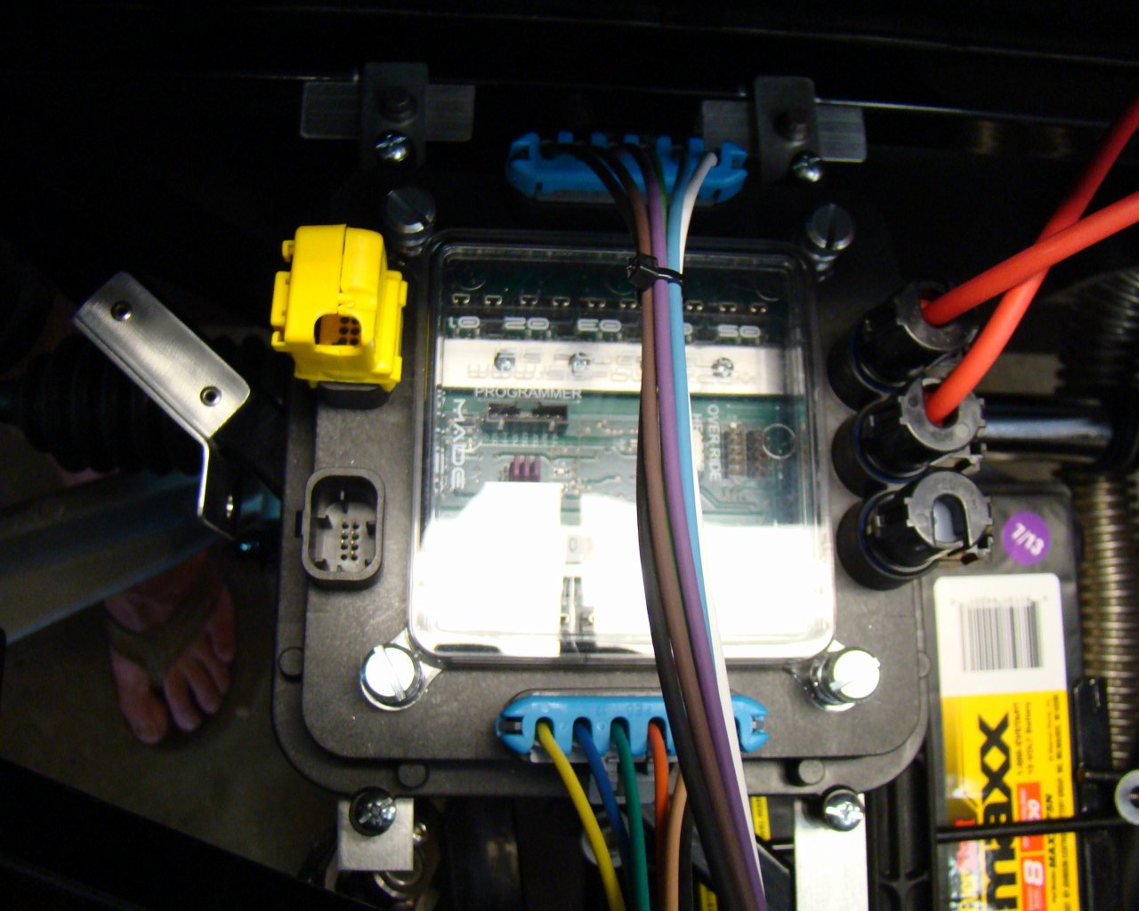
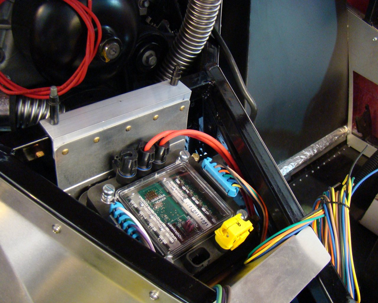
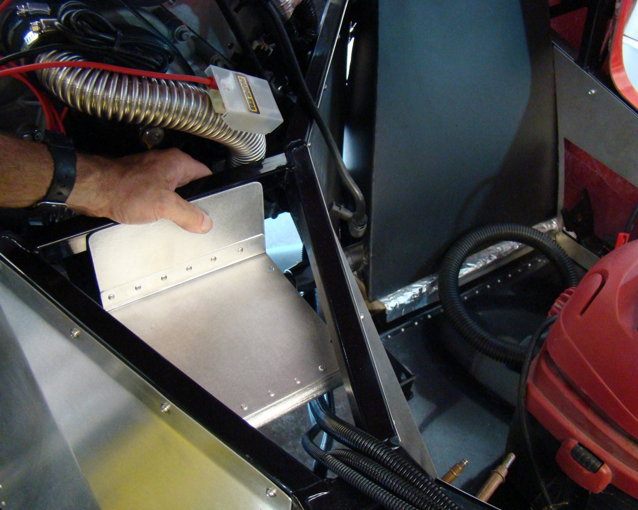
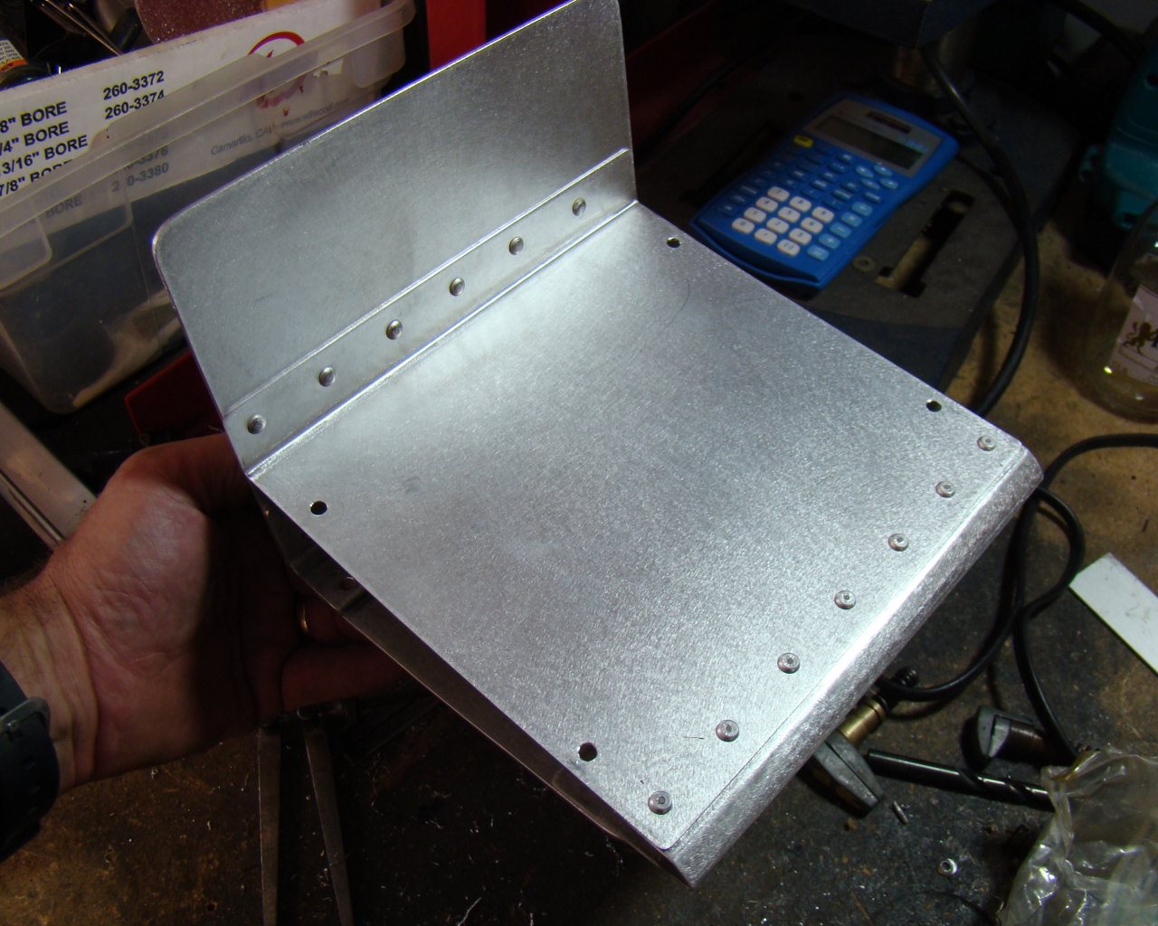
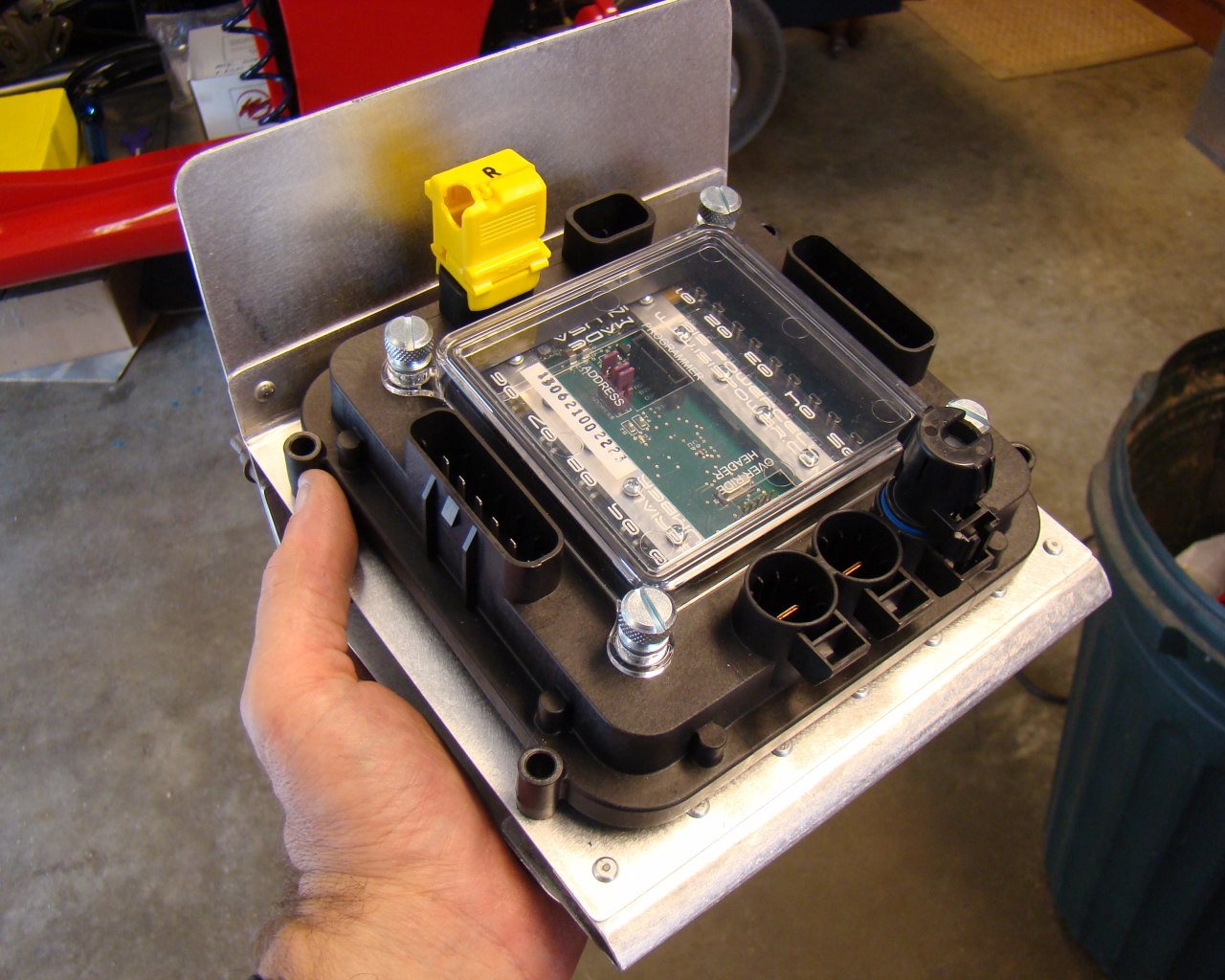
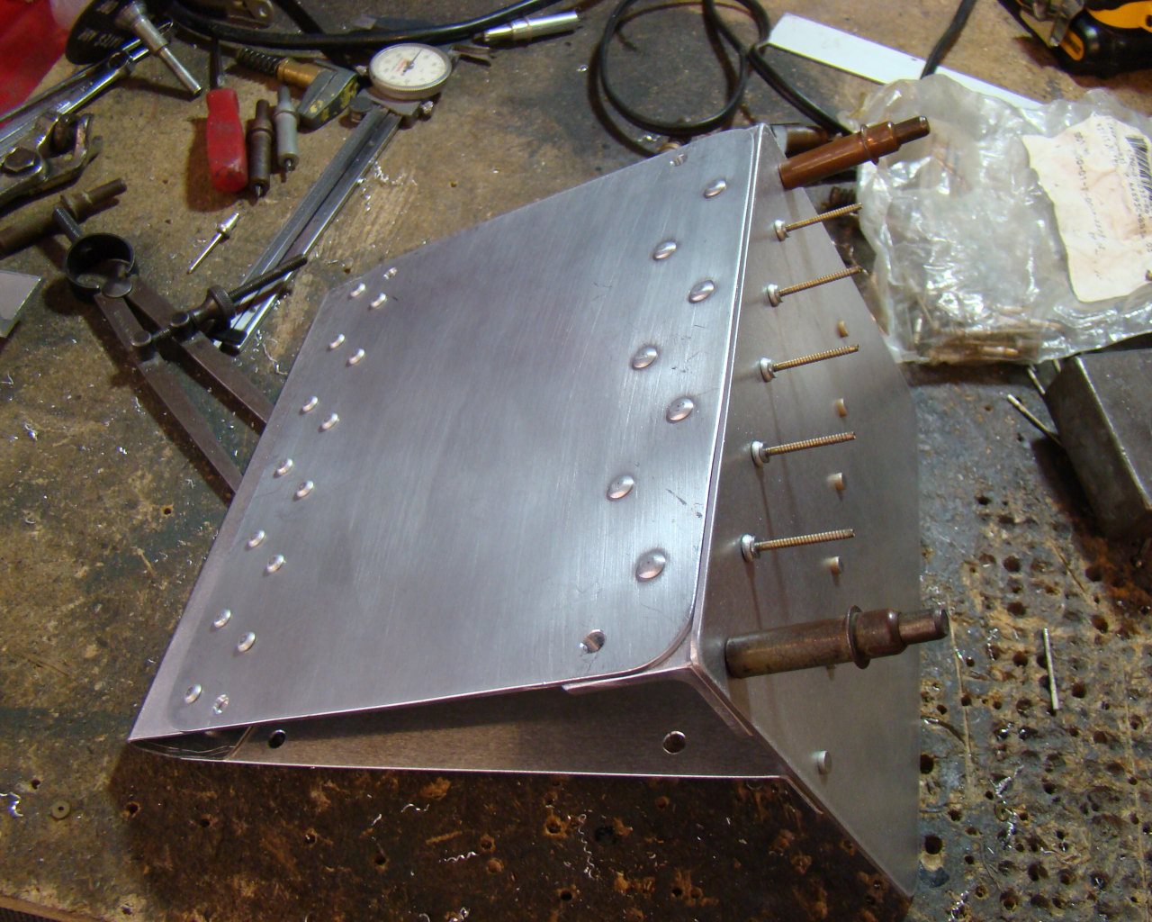
This is the ISIS Master Cell and Forward Power Cell. I mounted them just forward of the firewall, accessible by lifting the hood/front end and leaning in to program the system. The aft Powercell is mounted beneath the engine cover and accessible by removing the cover between the seats. In both cases, I had to build a shelf and brackets from sheet metal. I purchased the aluminum from Online metals. They sell various tempers of aircraft quality aluminum sheet and extrusion for very reasonable prices..
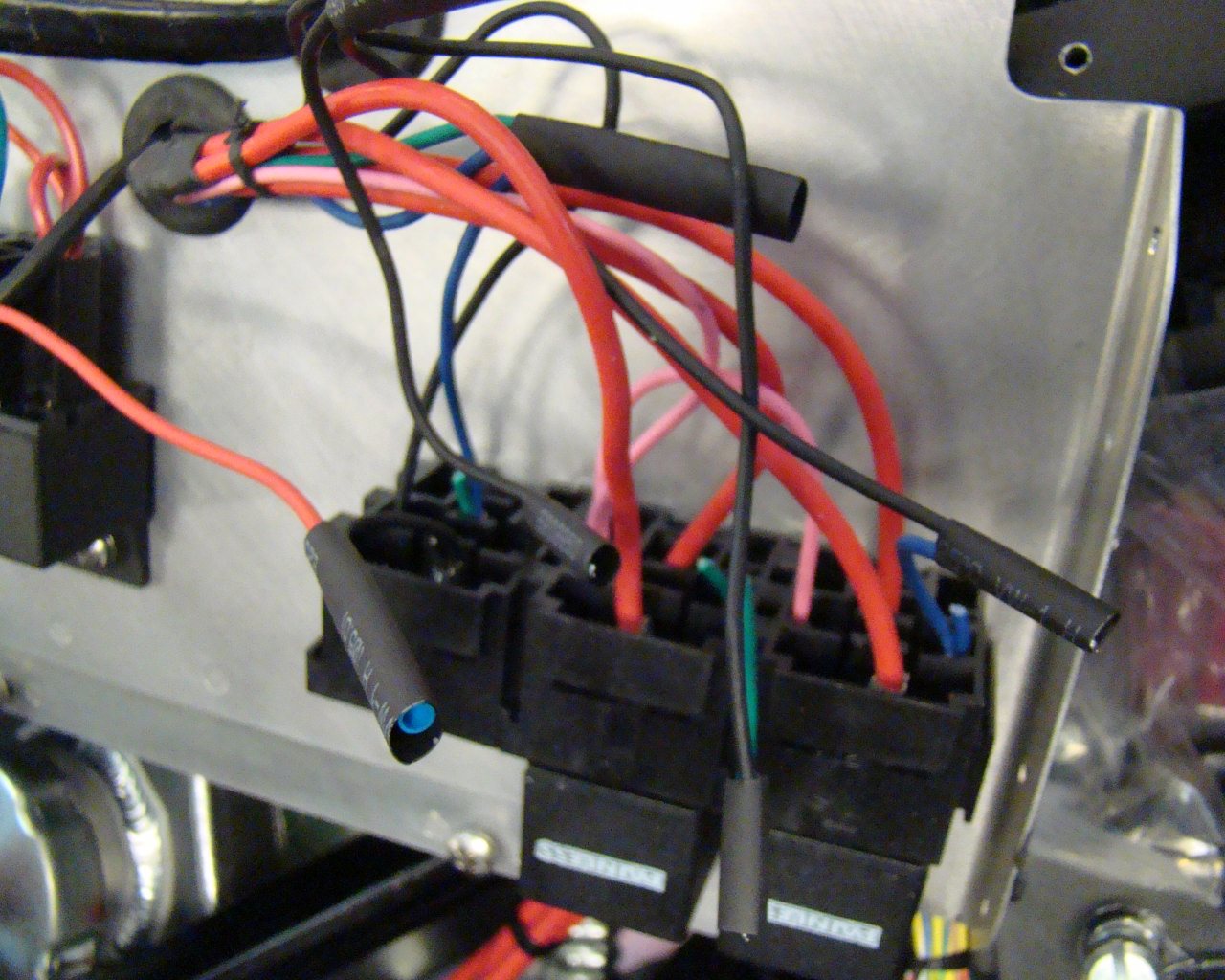
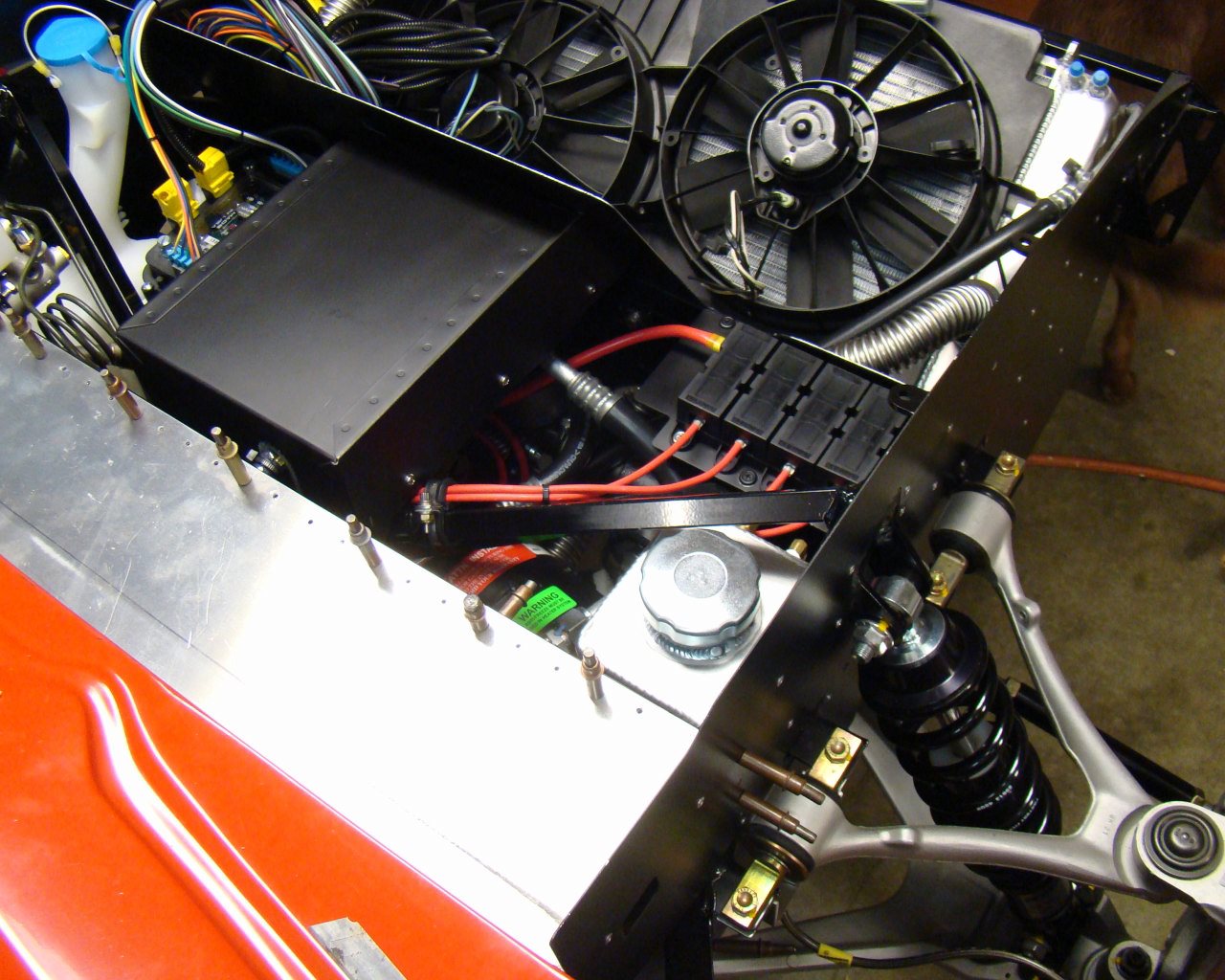
The Powercell is to the right. The Mater Cell is centered and the relays to the left are for the forward and aft Powercells,
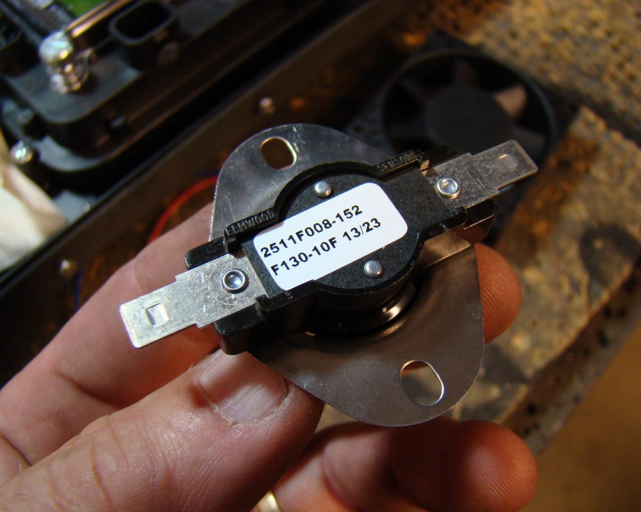
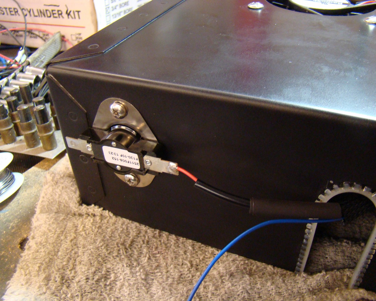
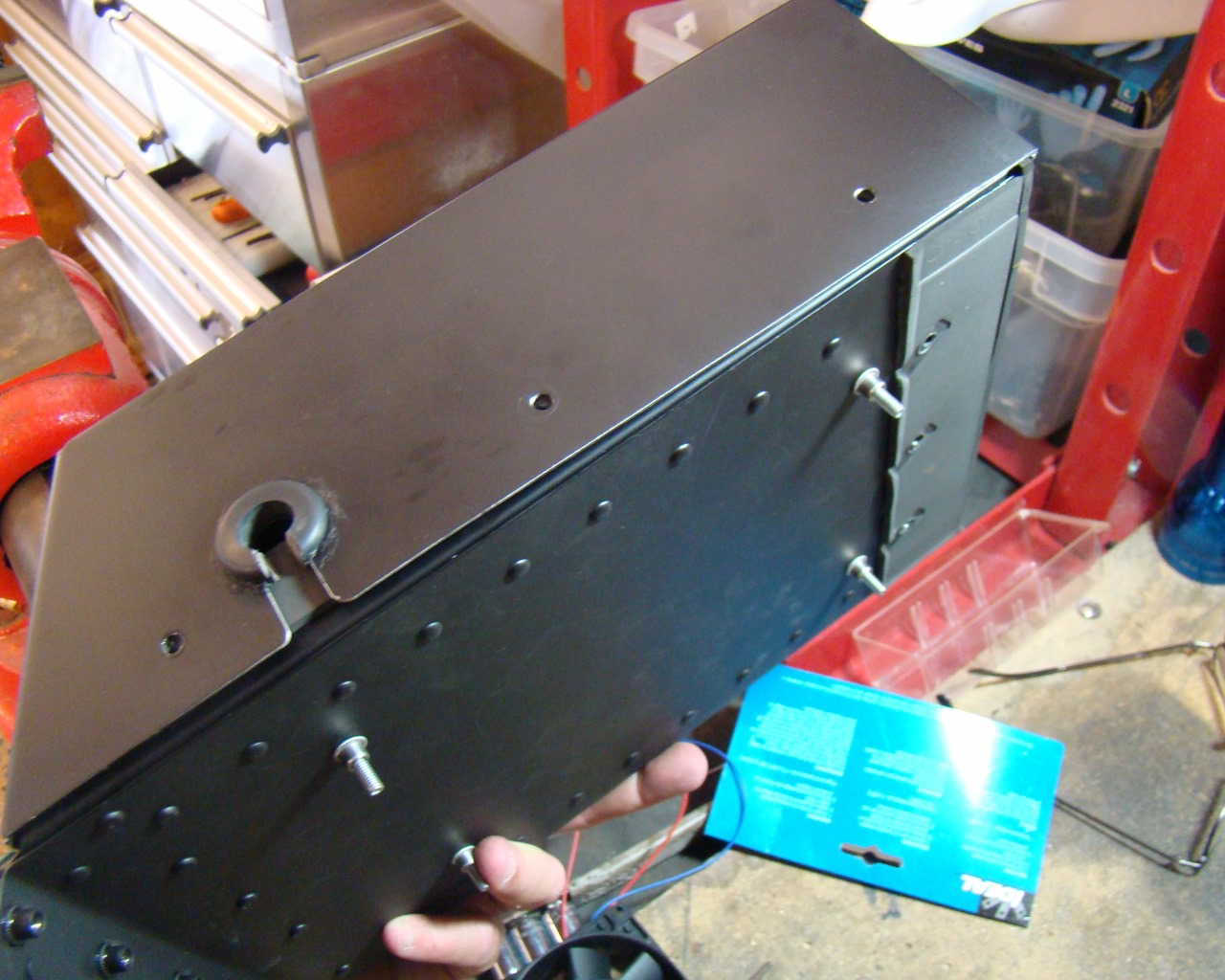
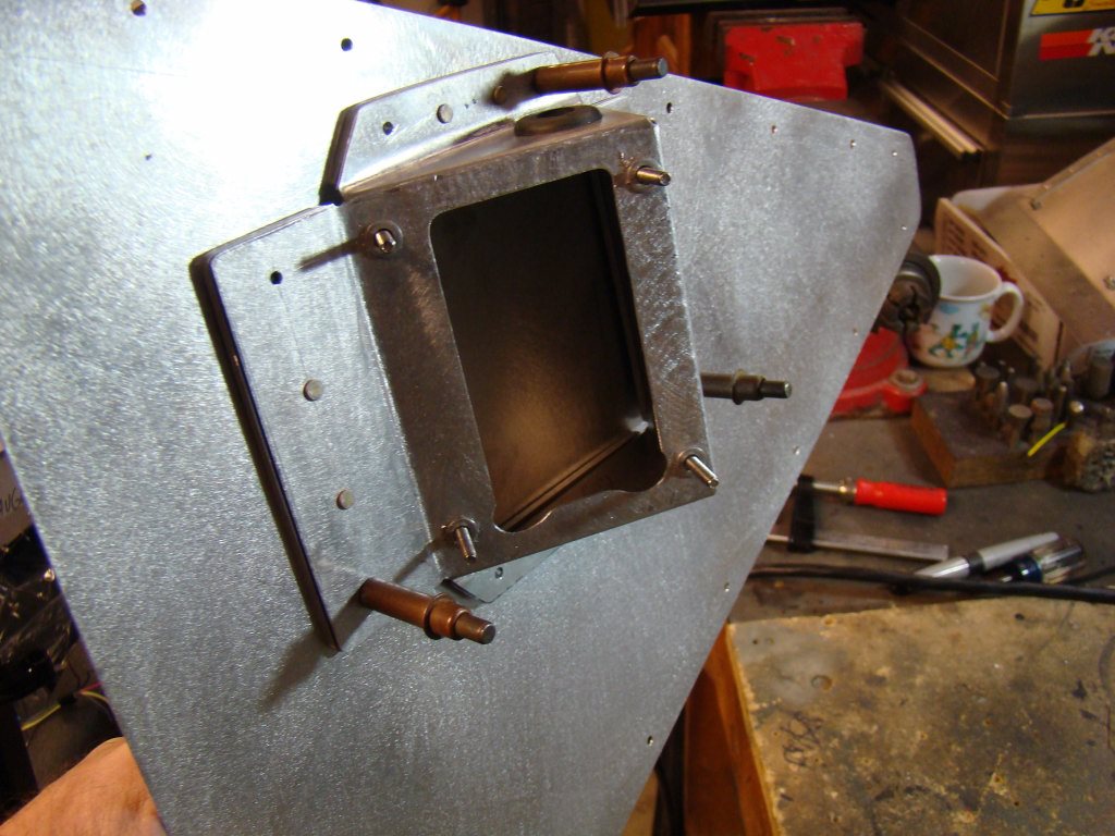
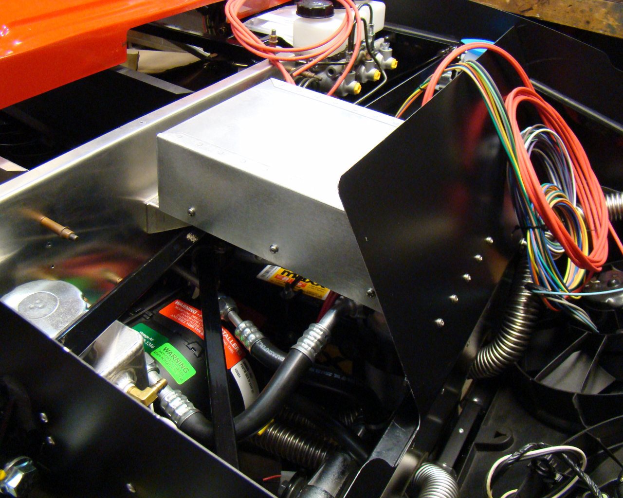
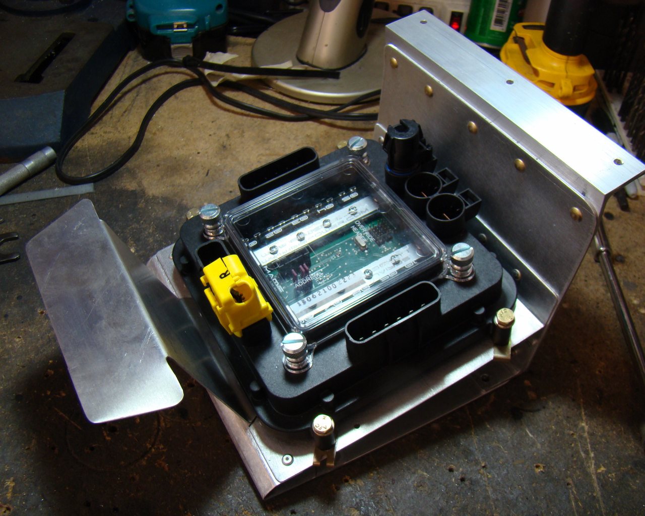
The Master cell cover was originally sealed with mount holes. Once I added the Fan and thermo switch, I drilled holes in the cover floor to allow cooling air circulation
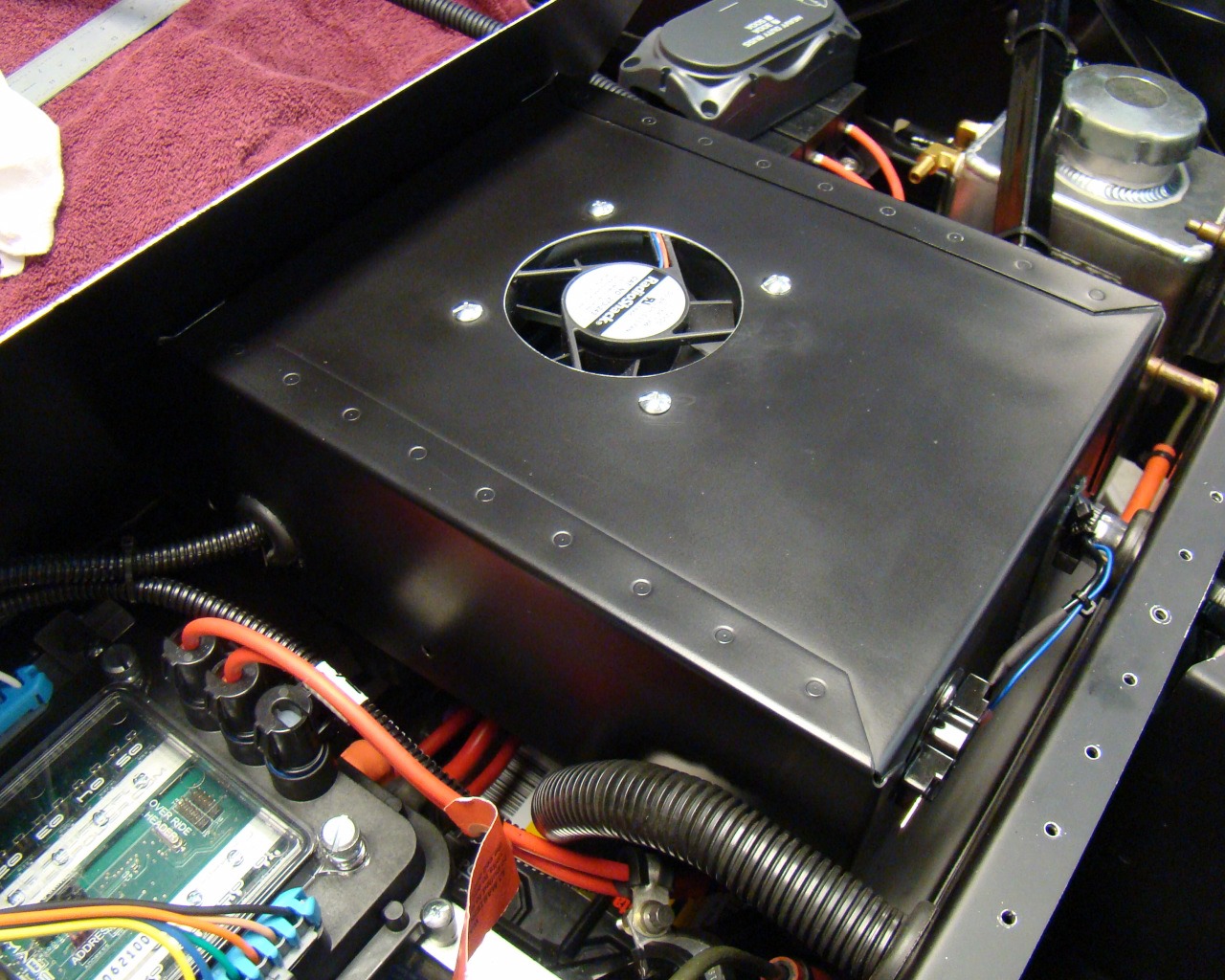
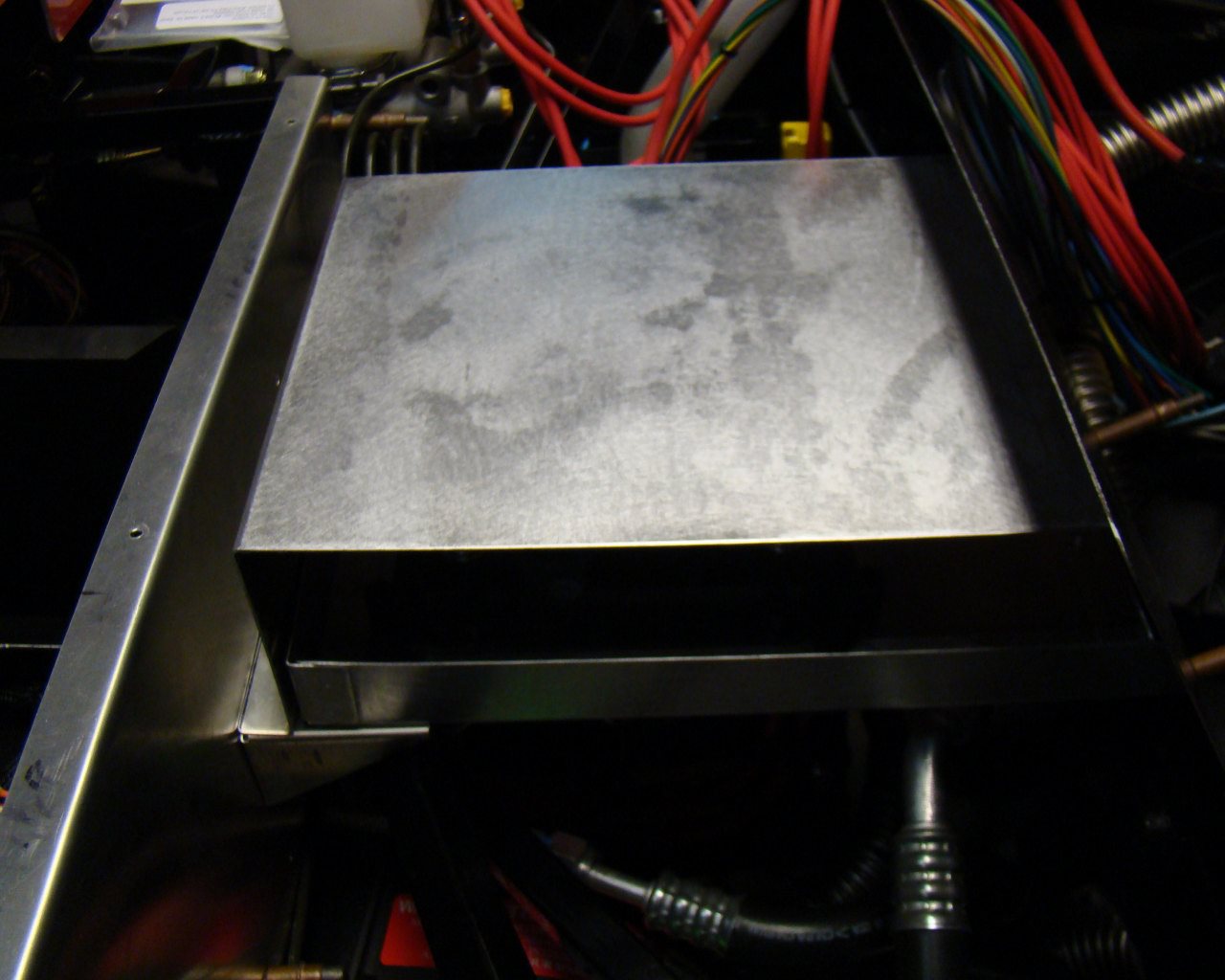
There are several pictures of the ISIS Master Cell cover in this page. At different times, I worked on the box so they are not all in order. Basically the box has come out for changes. The first was a basic cover. Then I added a fan and thermo switch rated slightly below the 85C rating of the Mastercell. I painted the box with Eastwood 2K Ceramic which is HARD as HELL and I ended up a little too heavy. I pulled it out again and am about to sand and re-coat to match the other panels. When I did, I added the aluminum grill which is .063 aluminum with 3/16ths perforations. (Lower photo) There is a grounding terminal block that utilizes the sheet metal cover mount screws mounted to the right side of the box. Just to the right on the fire wall is the InMotion Megafuse. I also fabricated a filler panel for the opening that the C5 overflow reservoir would have been mounted. I closed this off to keep airflow directed up through the front end louvers in the hood. Fan wires are routed through it and re-pinned with Delphi Metri-Pak pins and new painless wiring GM connectors..
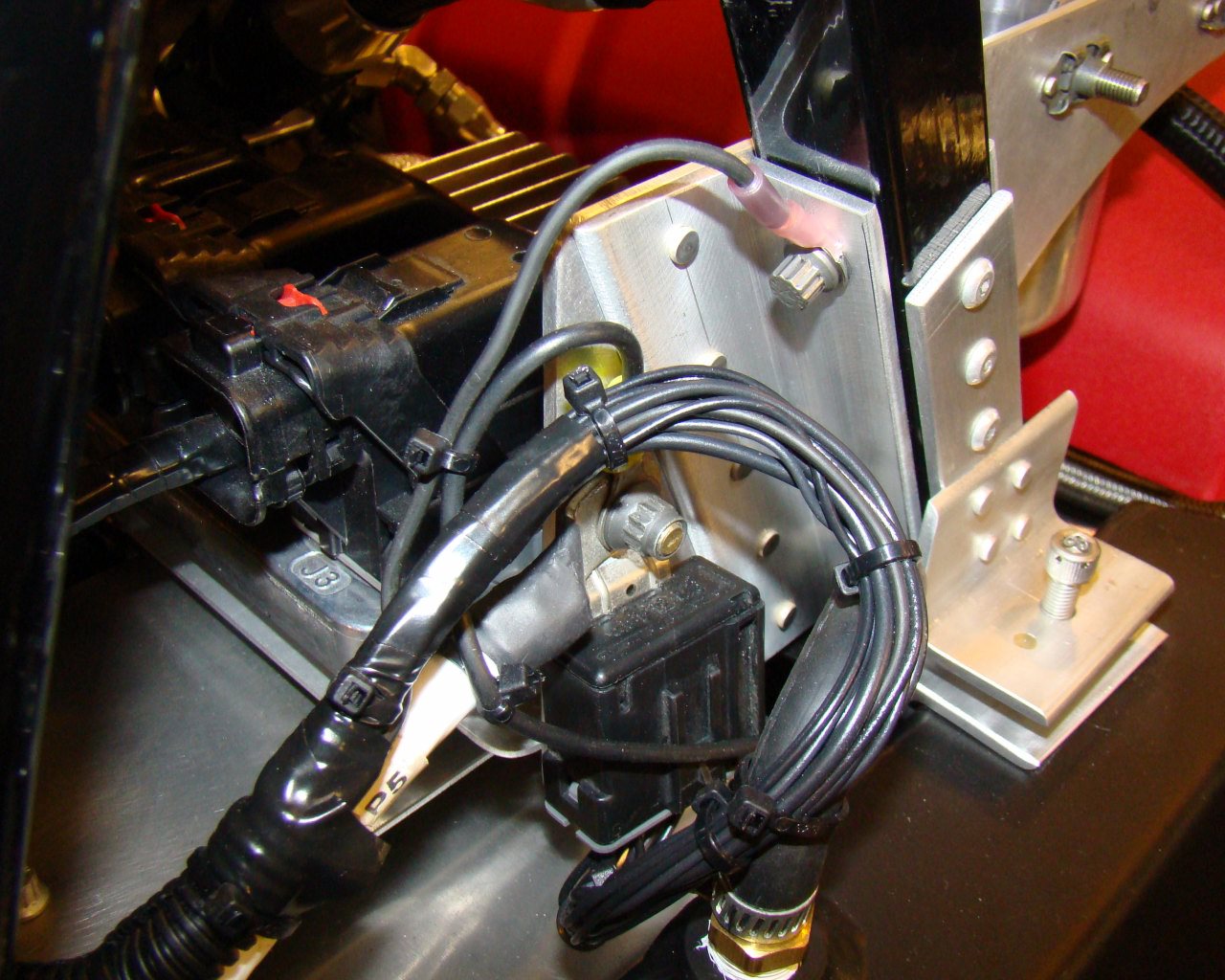
II used the C5 Corvette ground block for a centralized grounding point near the aft tank. There are many of these in the Corvette and they can be re-used. Under the cover, there is a u-shaped metal contact which is common to all black ground wires emanating from the block. They come in handy and do away with the need to use terminal blocks. I ran an 18 GA ground wire from the negative battery post and connected it to the Aluminum breather tank mount plate for added grounding integrity.
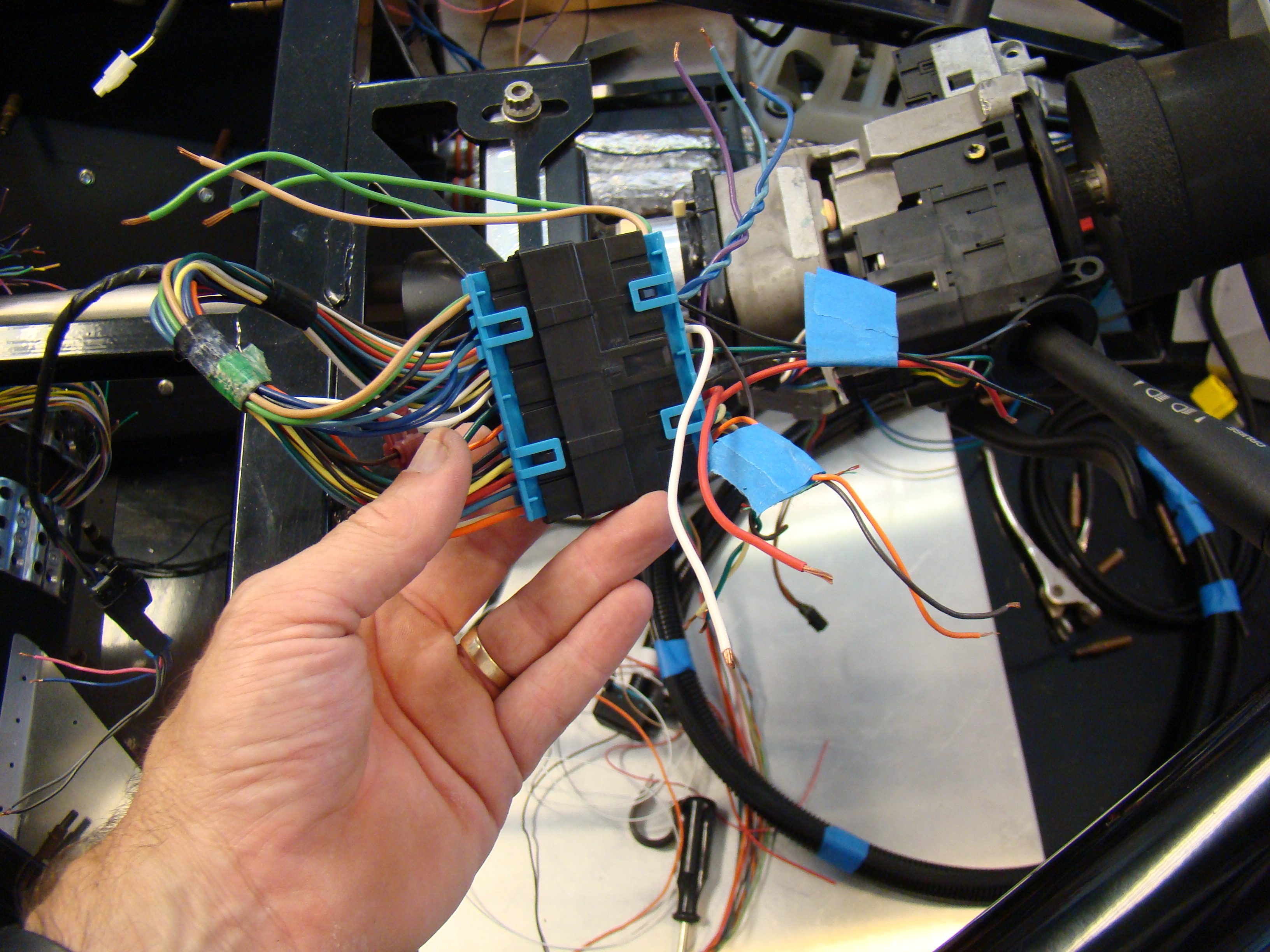
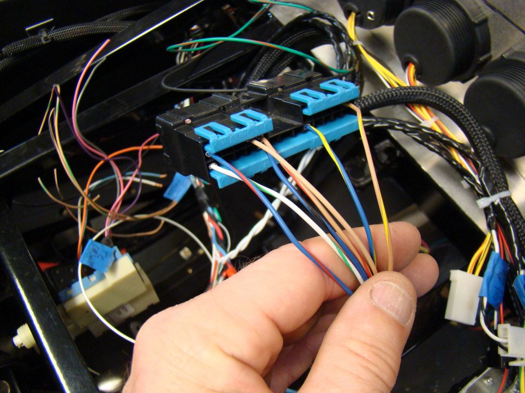
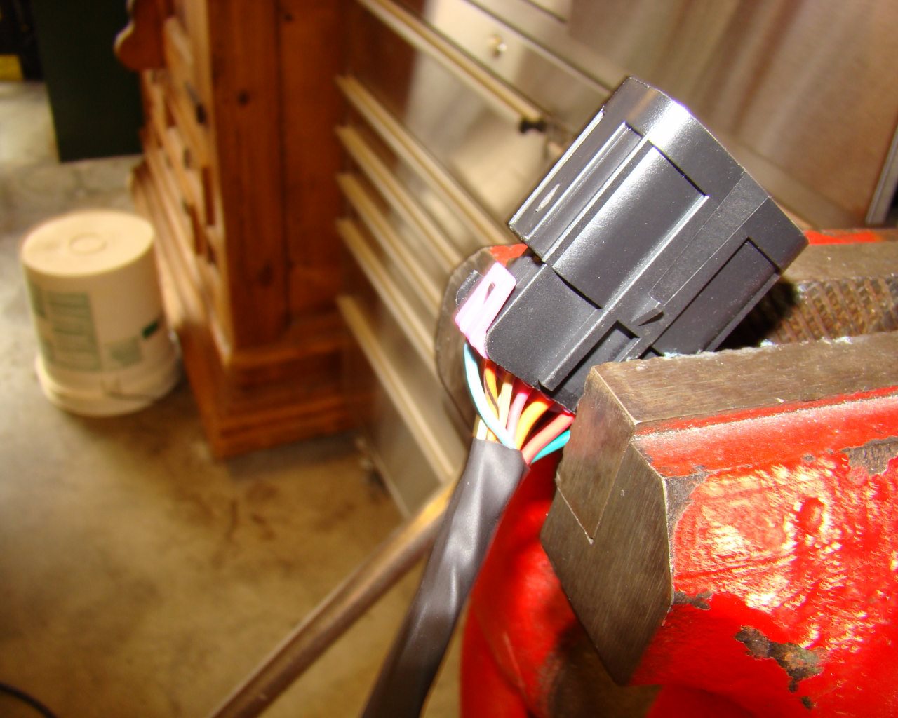
This is the steering column connector. I used a Multi-Meter to determine the pin/terminal functions. To do this, you simply find the common grounds and begin manipulating the various switches on the column. Also, the Corvette service manual has the pin-out for this connector. I plan to re-pin one side with the 22 GA ISIS Mater Cell wires, thereby assigning switch functions for transfer of voltage via the Power Cell to each component.
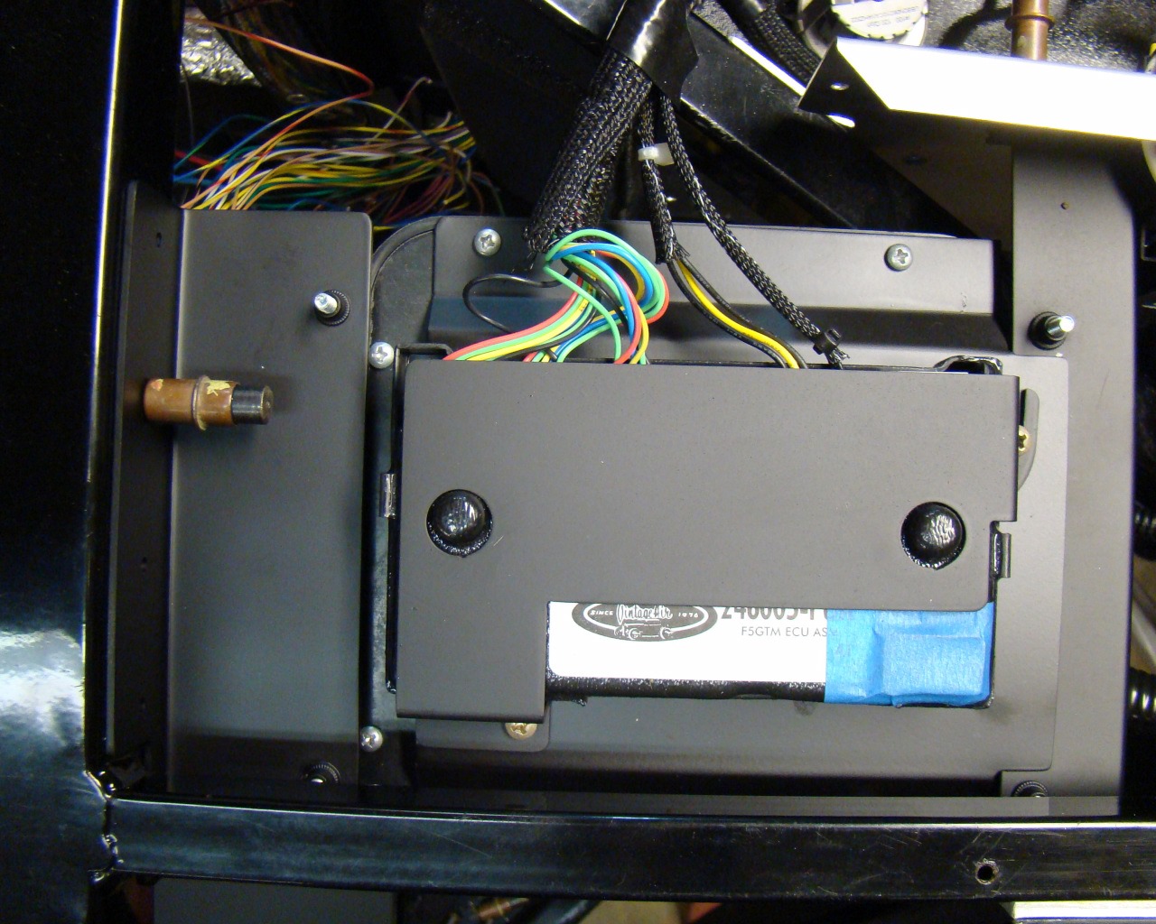
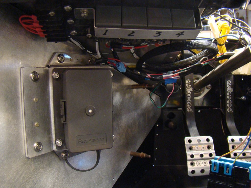
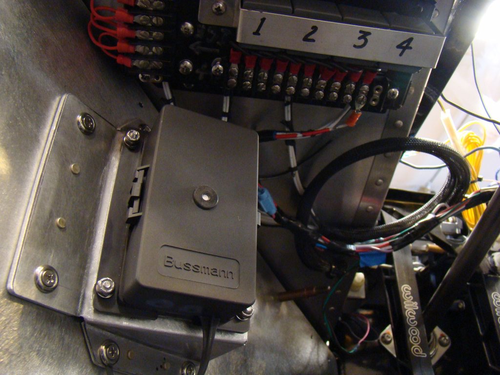
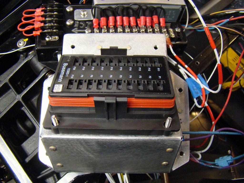
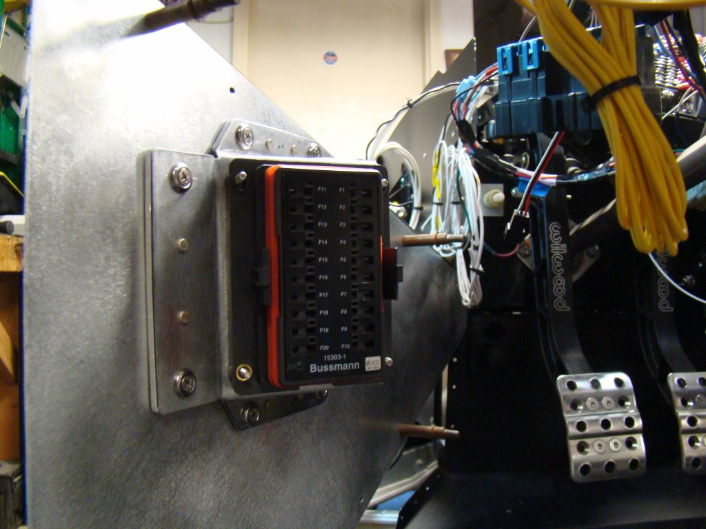
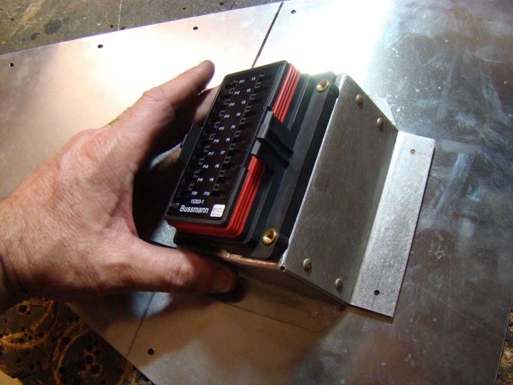
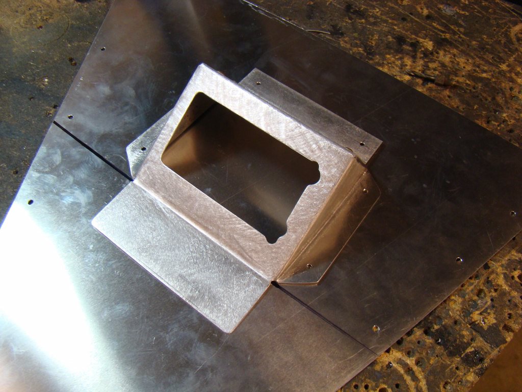
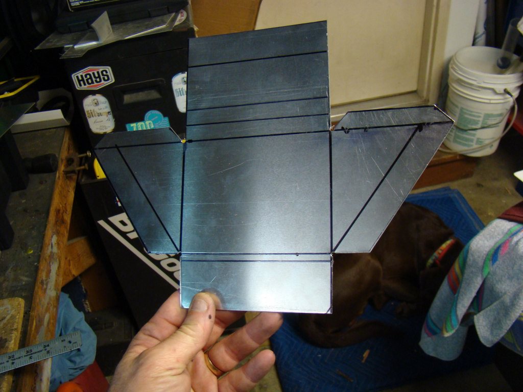
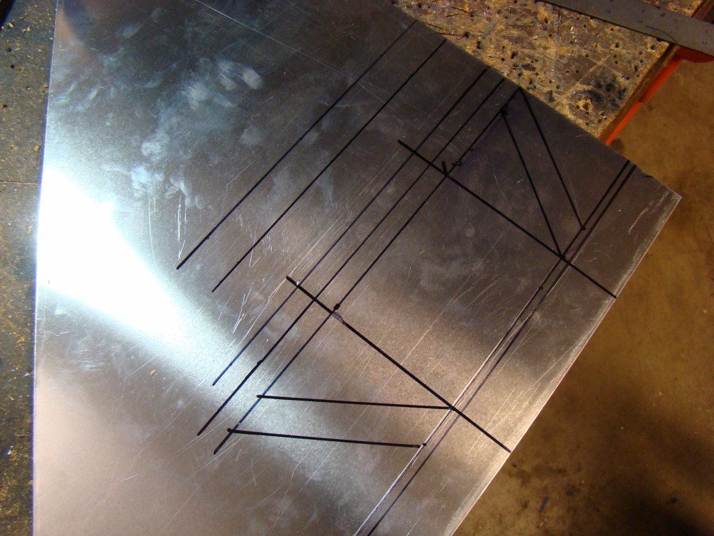
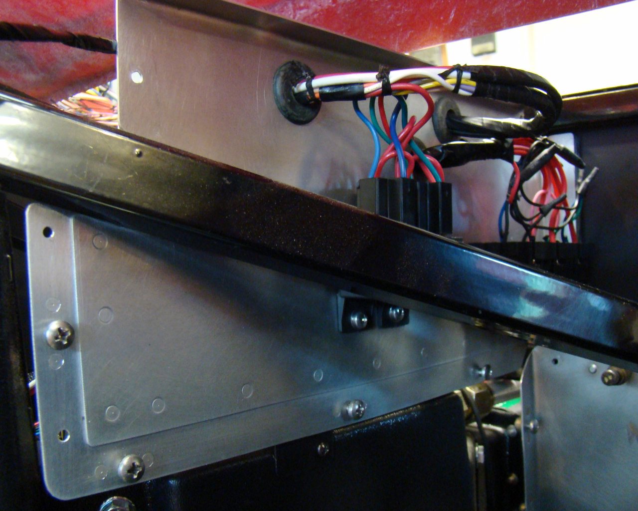
This series of photos shows the Vintage Air controller box. I unscrewed it from the Vintage Air unit, which when mounted, caused the controller to be up against the passenger foot box side panel. This would make it difficult to attach the harness plugs and could result in chafing on the small wires that are plugged into the box later. Access in the middle area under the dash will be limited due to permanent mounting of sheet metal panels and interior components. The stock harness length of the Vintage Air controller seems long enough to mount the box in a different location. In the pictures you can see that I made a formed sheet metal back panel which picks up the bottom IN Motion controller cover. This sets the height of the AC controller about 1/4" above the surface for heat dissipation. I used riv nuts and angled aluminum so that the unit (IN Motion and Vintage Air controller) can be removed with a screw driver from the passenger foot box area accessible after the car is assembled. The entire assembly remains below the sheet metal cover that installs over the top of all three under-dash locations.
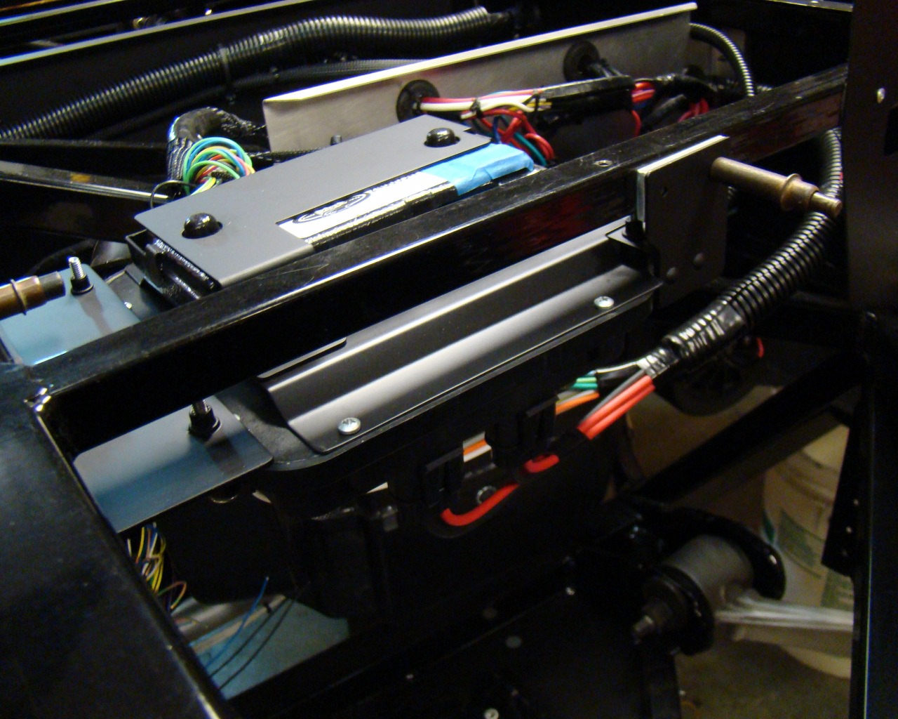
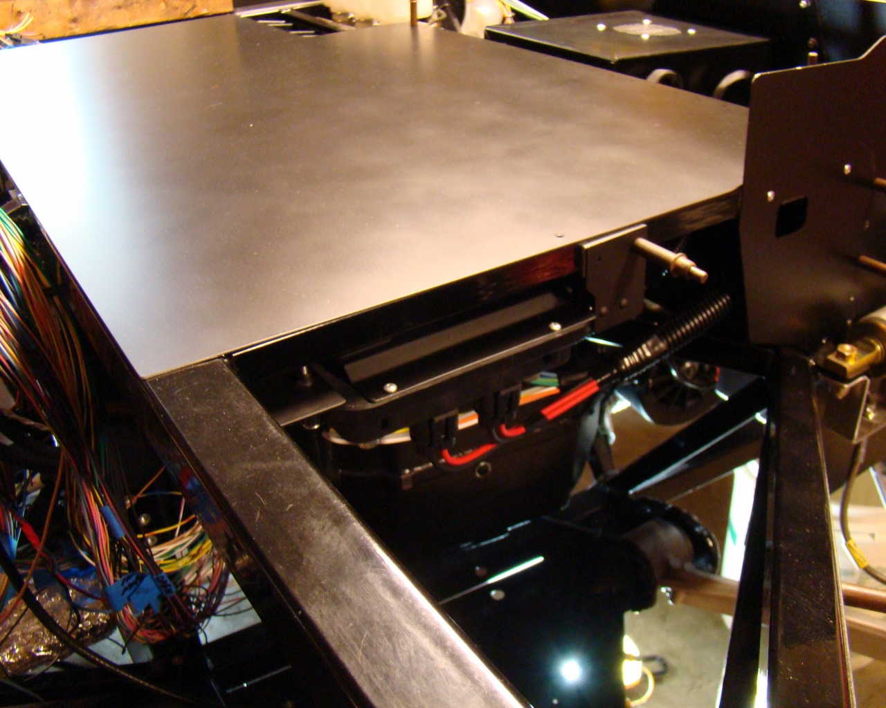
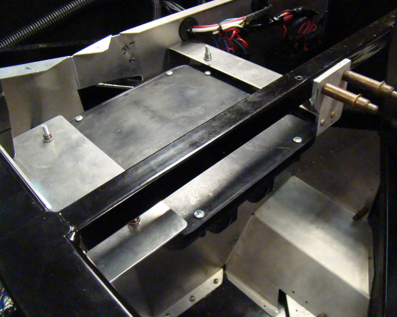
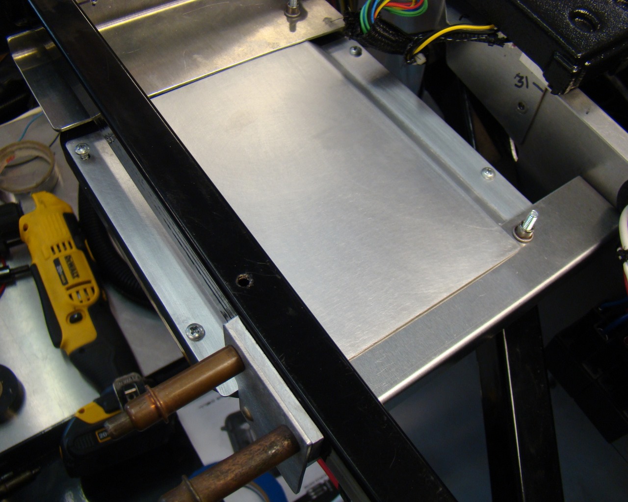

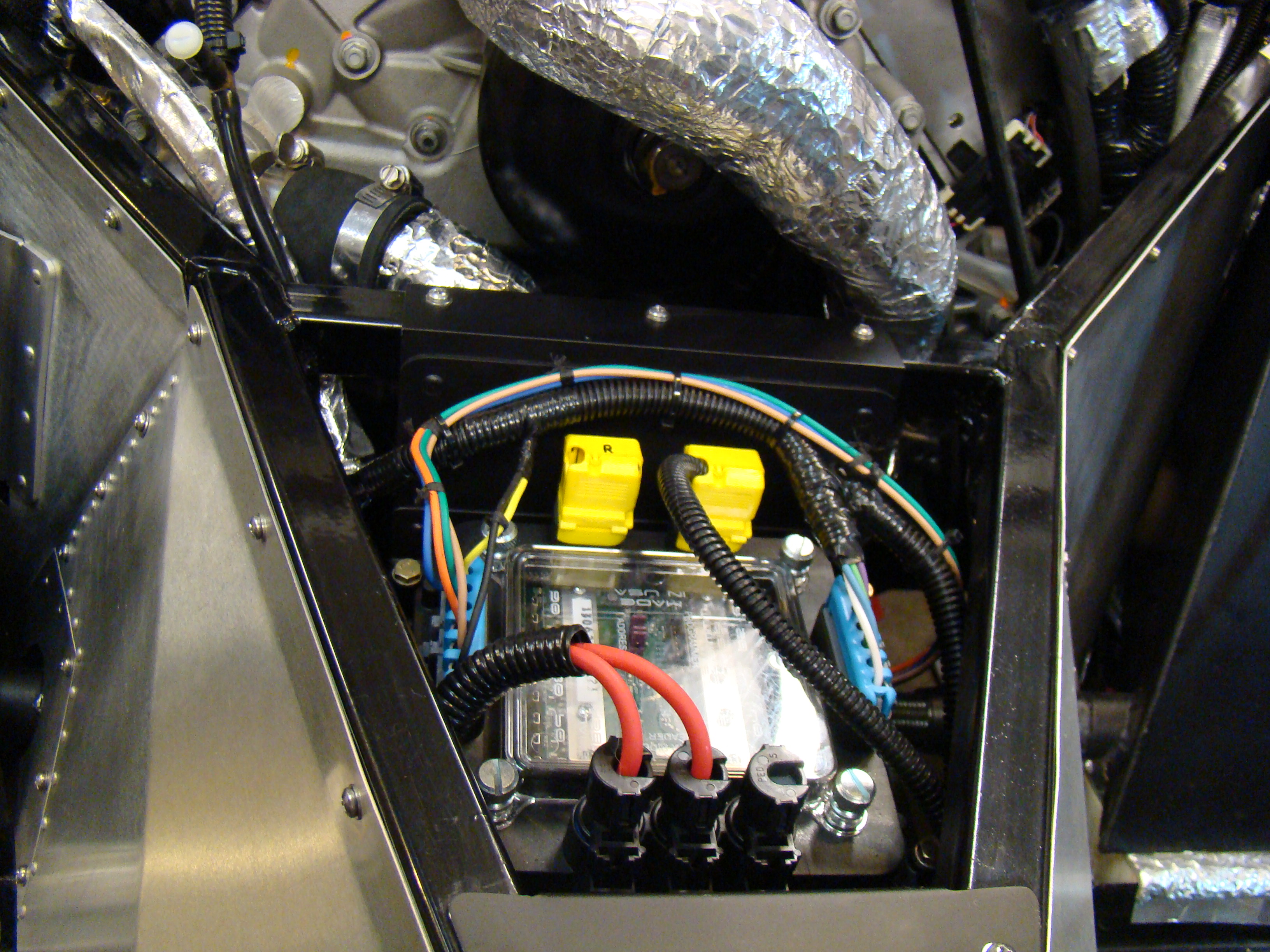
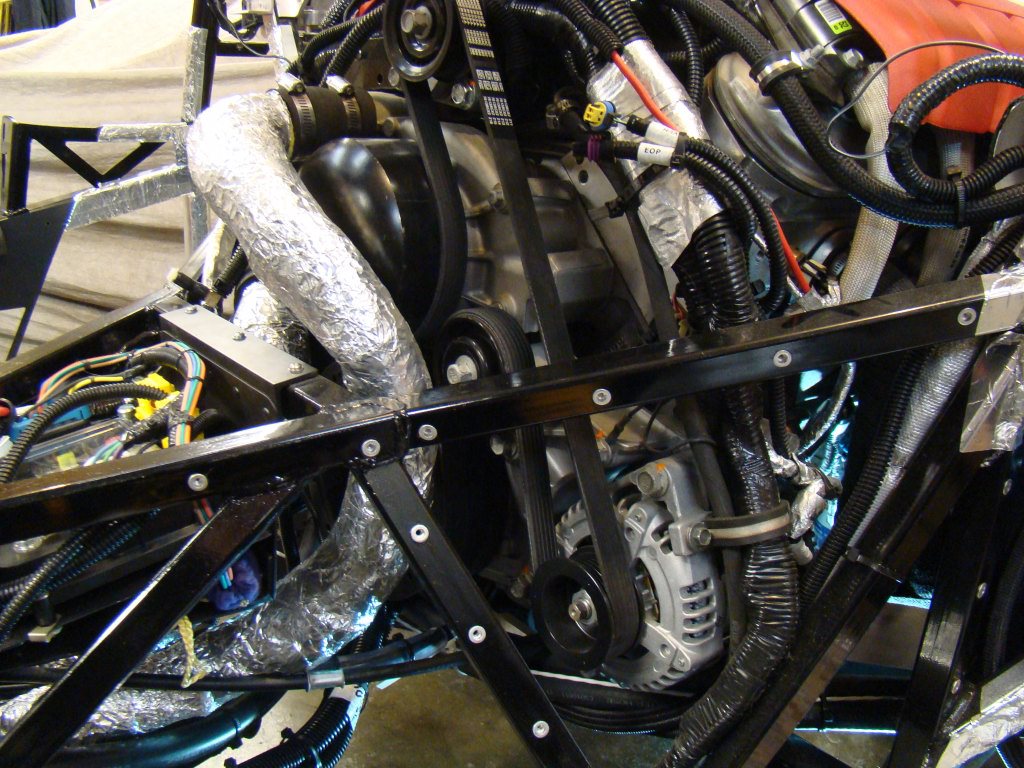
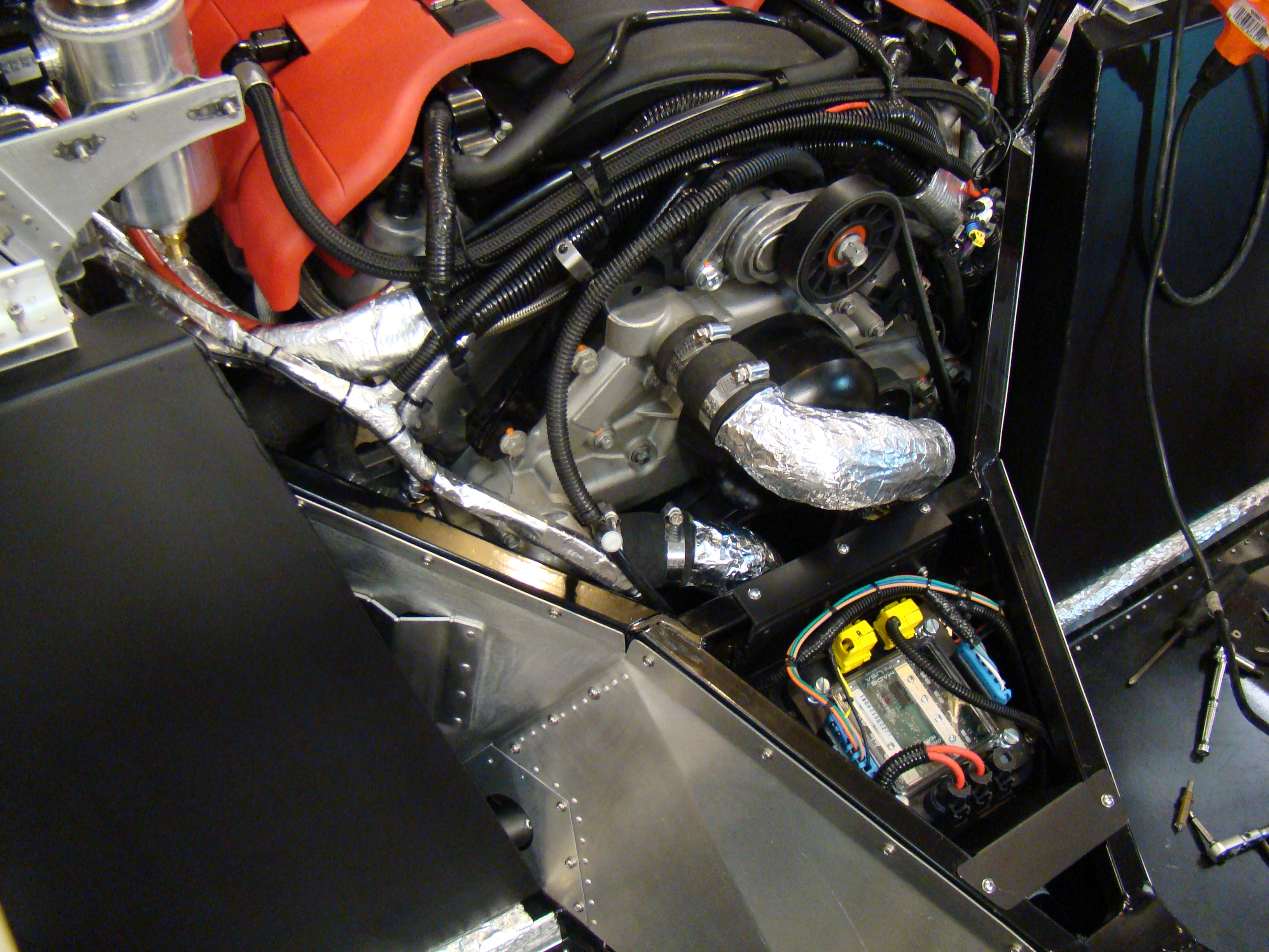
This is the aft Power Cell mounted just forward of the engine. I wrapped the water pump lines with Fiberglass insulation and foil tape. Beneath this unit I attached nut-plates (threaded inserts) for the Painless Wiring Mega Fuse holder and the heater control valve. Both mount effortlessly to the bottom of this mount. The black "T" with the white cap is the Manifold vacuum line going to the heater valve.
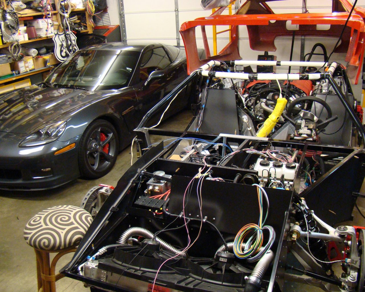
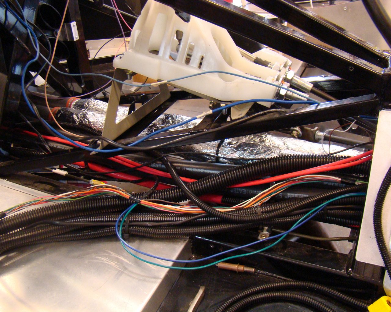
The harnesses going through the tunnel. I separated the harnesses and tried to keep signal wires away from the power wires to the extent possible. All of this cleans up pretty well once the loom is lined up through the tunnel. Yes, there's a lot but it fits reasonably well. I pinned the LS stand alone harness bulkhead connector with all options and ran it forward as well. The ECU harness, ISIS cables, Traction Control wires and diagnostic connector, fuel tank wiring, gas pedal harness and other signal wires all route through the tunnel in this build.
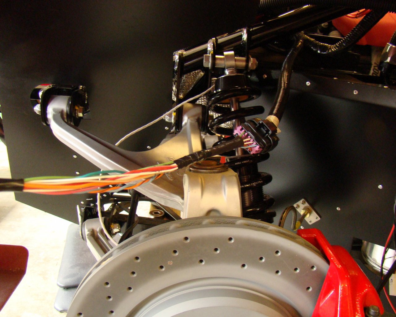
This is the LS7 bulkhead connector which comes with the ECU and harness kit. One side requires pinning so you will need the pins and wires. I ordered the pins based on the part numbers supplied in the literature with the harness. The wires were leftover from the Corvette. I stripped the entire harness and cut the longest length of the various colored wires for use throughout the build.

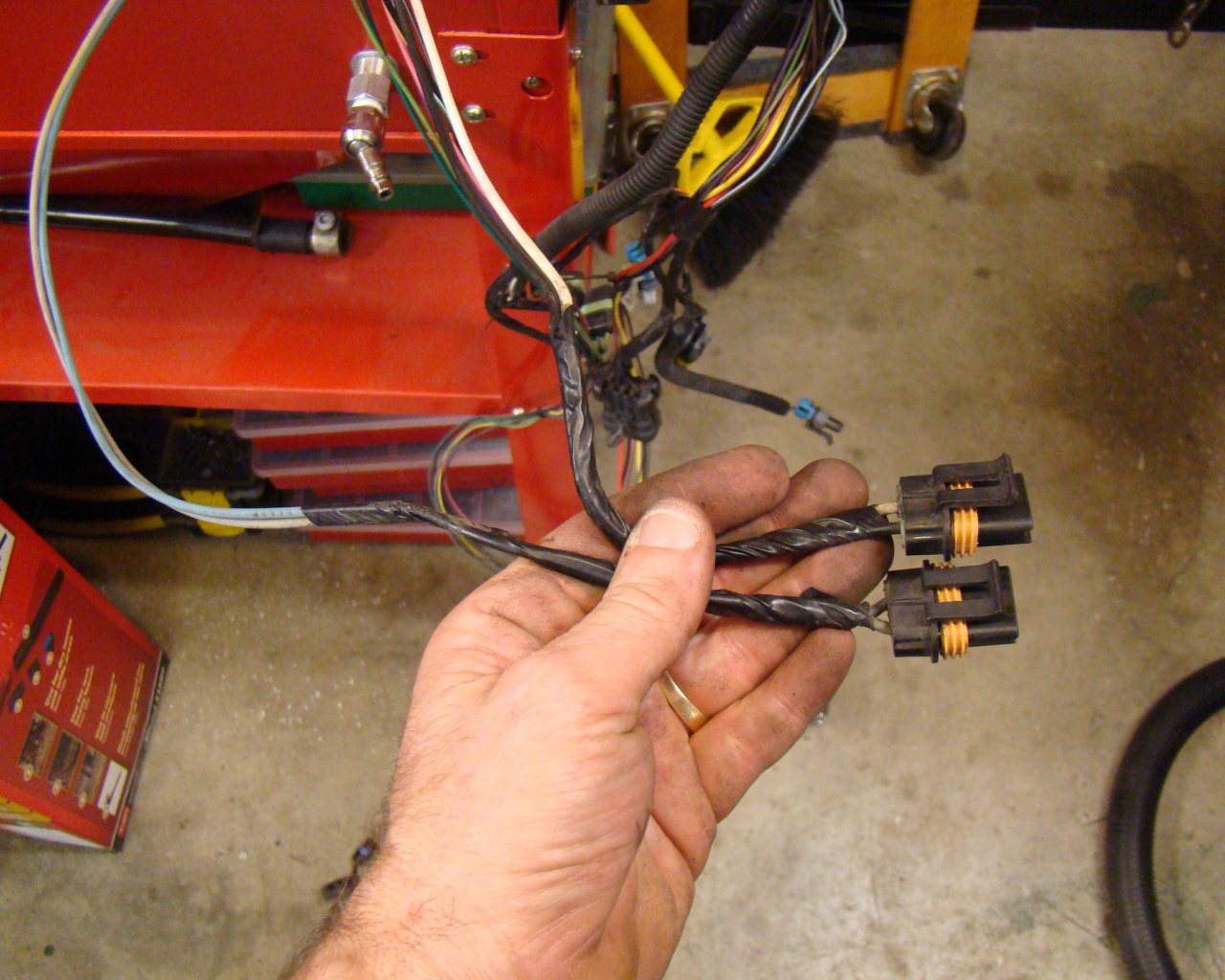
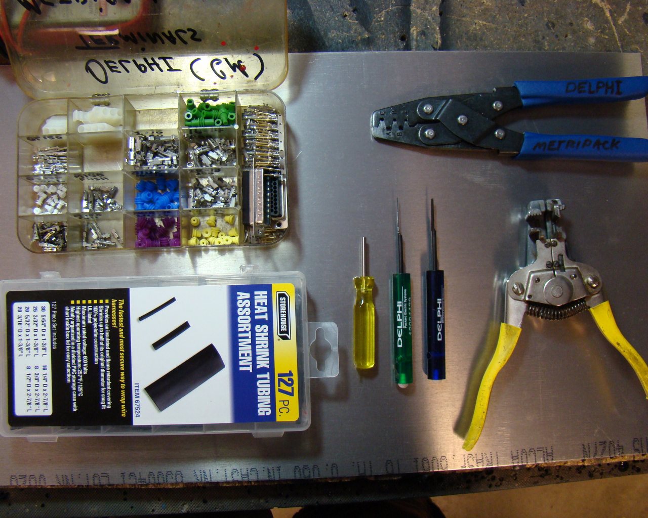
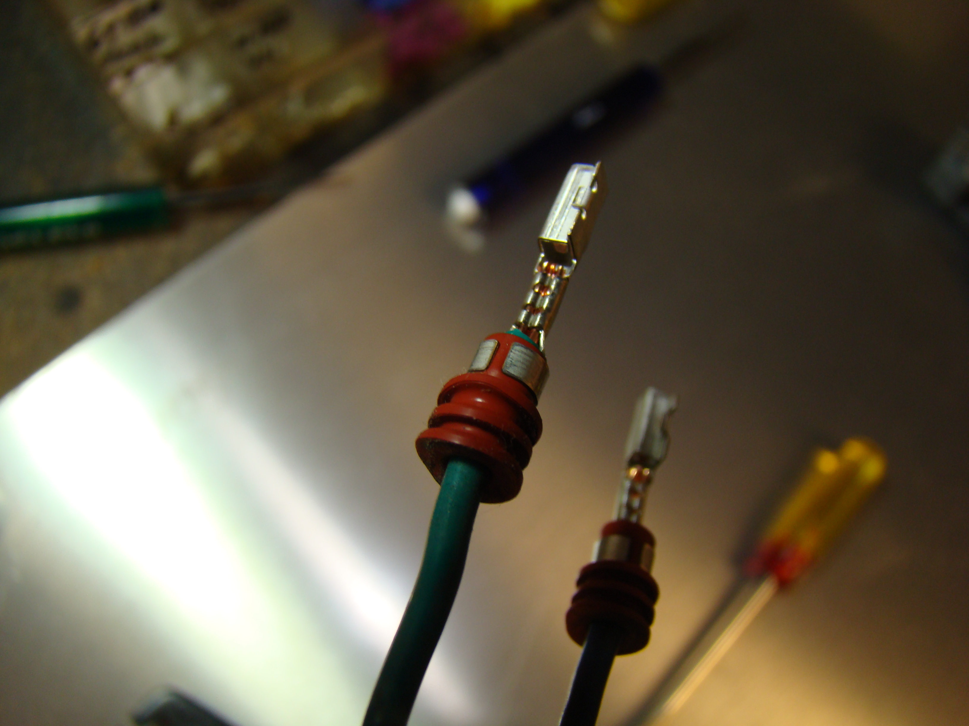
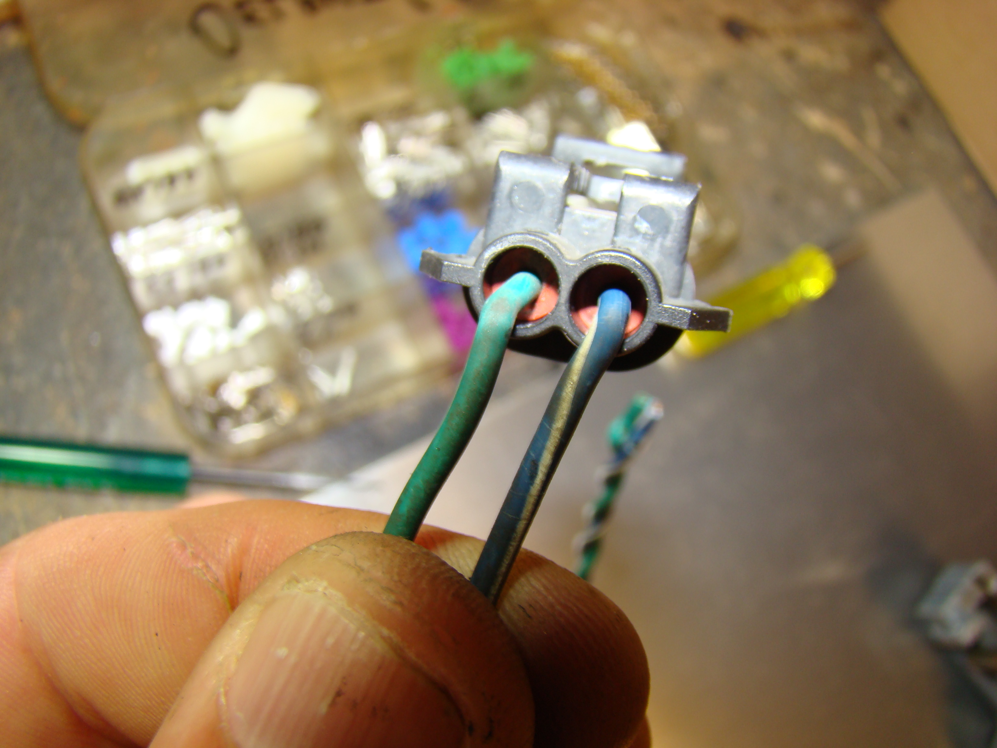
Above and below are a few examples of Delphi Metri-Pak and GT pins, terminals, weather seals and the tools needed to remove and install them. It is well worth a minimal investment to buy the tools and pins. By using the leftover harnesses from the Corvette, you will cut down on the expense of some really good plugs. This will prevent the need to use cheap terminals and splices during the build. It takes a bit to determine the right pin sizes but basically all the Corvette stuff is Metri-Pak, Weather Seal, and GT 150's and 280's. Go online and look up Ballenger Motor Sports in Mechanicsville, VA for decent prices on pins, terminals and tools.
ISIS SYSTEM COMPONENTS:




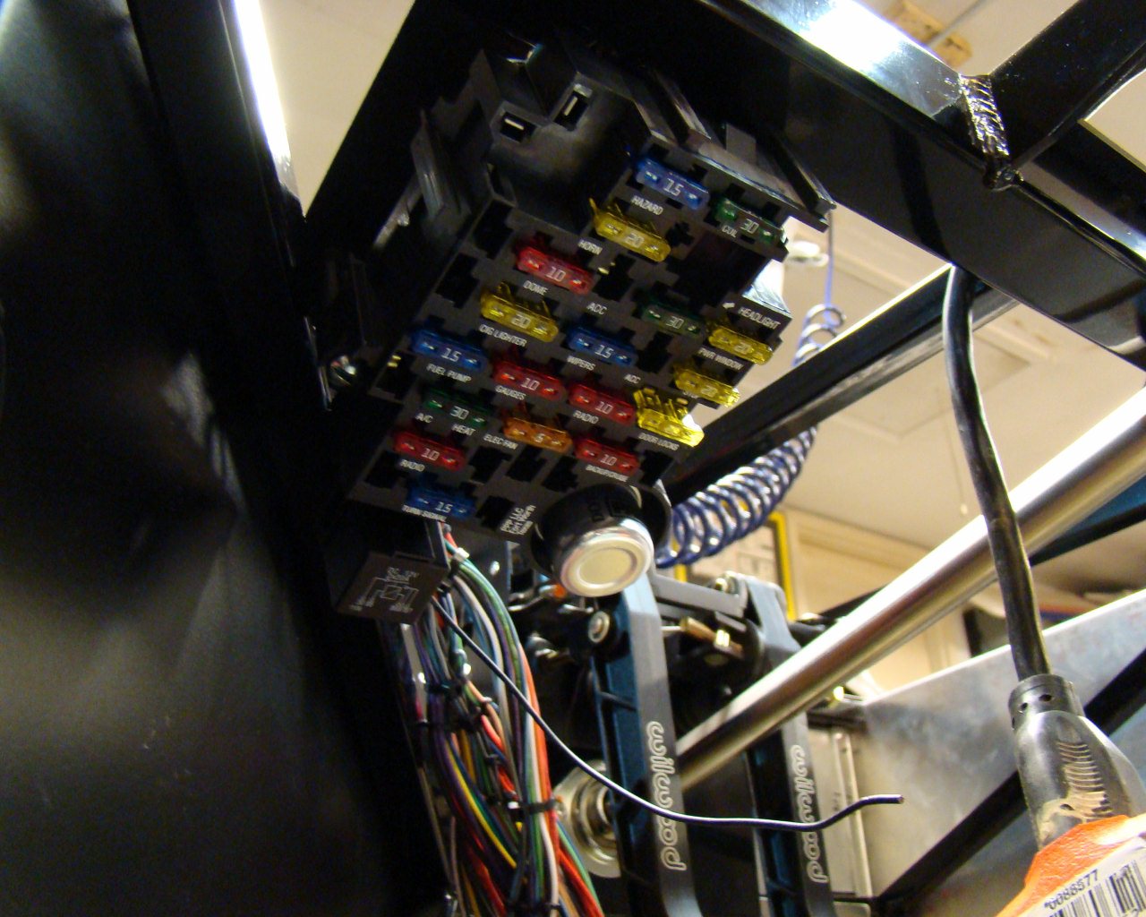
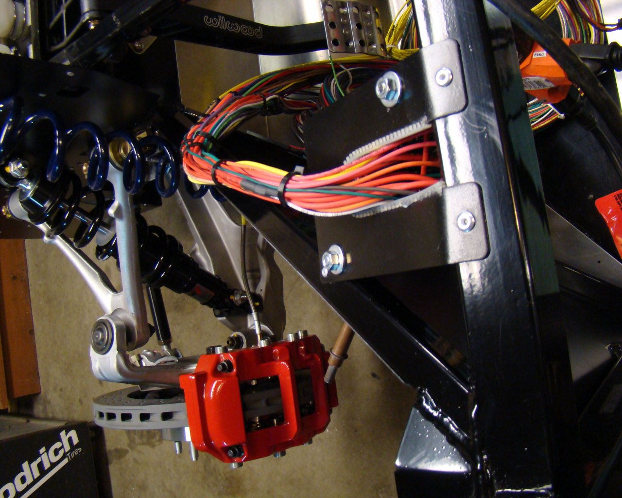
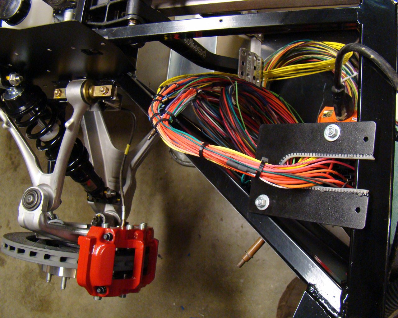
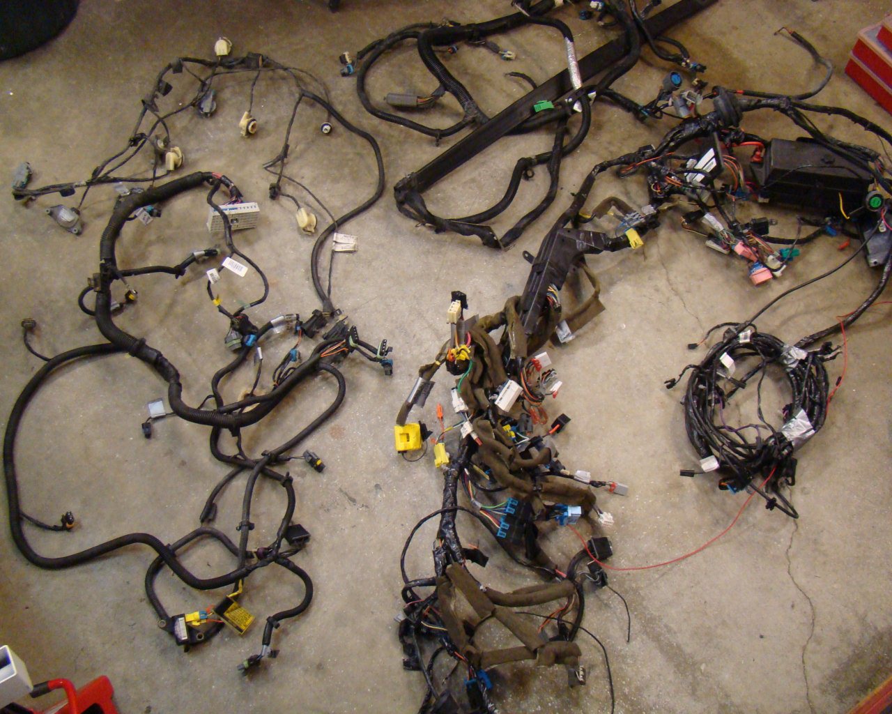
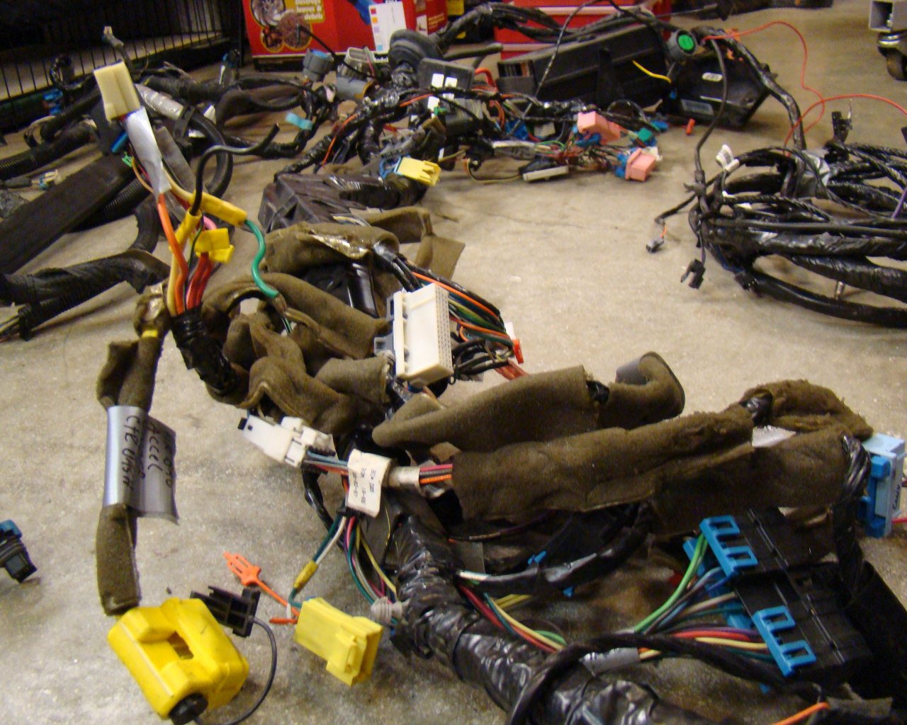
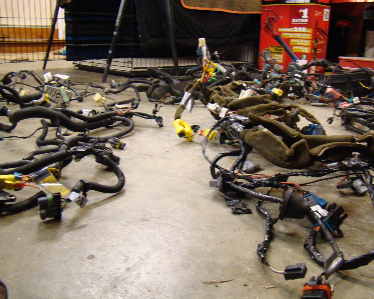
These are
the harnesses pulled from the Corvette. I'll need to strip
them, extract certain circuits and then add additional wiring to
completely adapt these to the GTM. Basically the manual walks you
through the basic pieces but it's still up to the builder to
doublecheck and verify using the Corvette schematics, wiring
diagrams, system interfaces and computer controlled circuit
descriptions. With the LS7 engine and addition of a custom
dash fuse box, AC system, entertainment system, instrumentation
etc, there's plenty thats not explained in the GTM assembly
manual. This is another area where character of the car
begins in the early build stages. Be sure to plan well ahead
to avoid cutting your way into the circuits later in the
build.
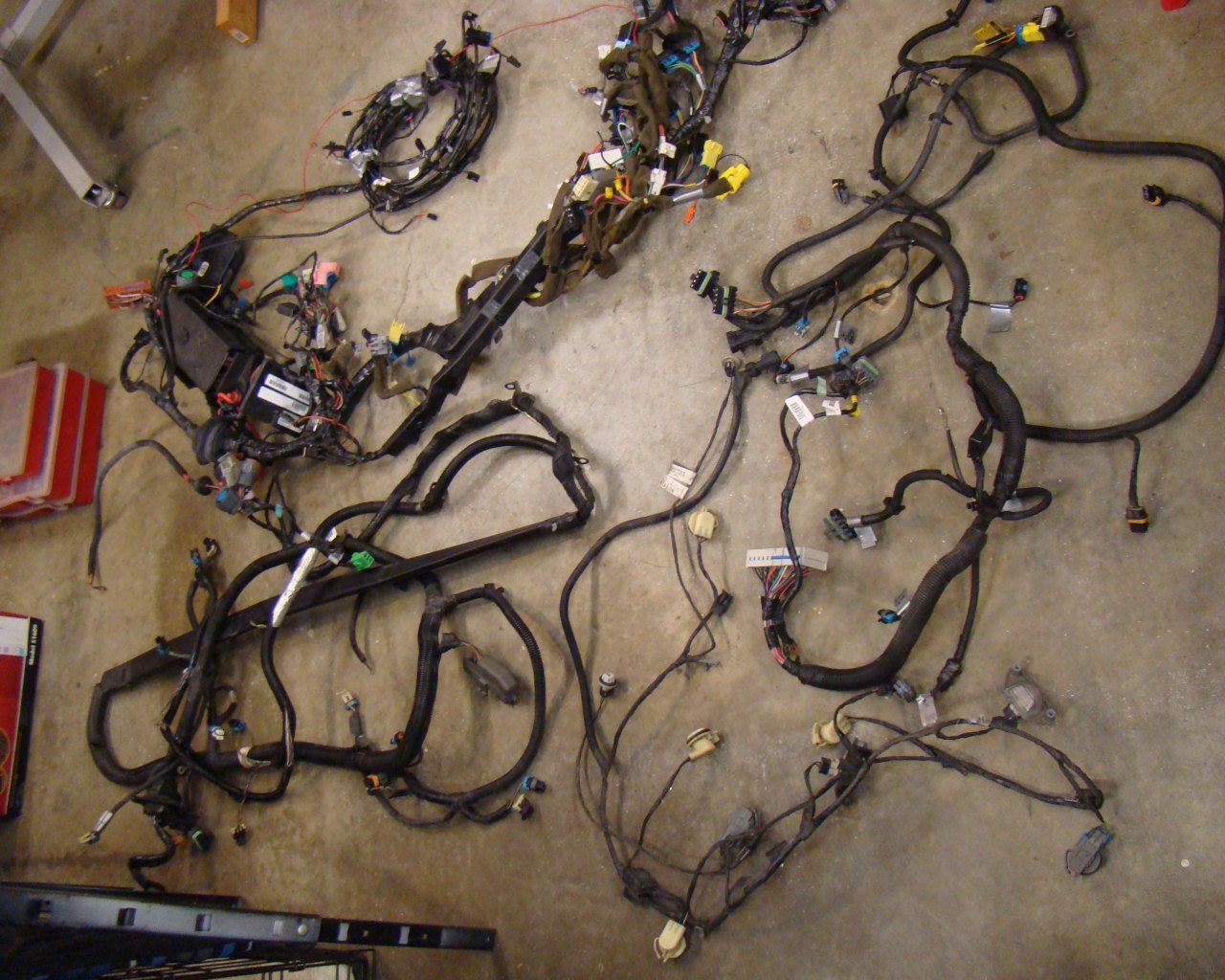
The harnesses shown here are for the chassis and dashboard and
include the under hood fuse box (minus the engine harness),
the back of the car (lights, fuel, suspension sensors etc) and the
front harness (lights, suspension sensors, fans, fluid capacity
sensors etc). The main engine harness and Engine Control Unit
(ECU) were kept with the LS1 engine. The engine and associated
wiring was sold and will be replaced using the GM performance
harness and ECU for the LS7 setup.
It's best to buy the Corvette repair and service manuals which
come in a set of three volumes. There are comprehensive
service instructions and parts assembly illustrations that are a
tremendous help when transitioning these parts from the Corvette to
the GTM
